AUDIO AND VISUAL SYSTEM > Dimmer Signal Circuit |
| 1.CHECK HARNESS AND CONNECTOR (RADIO RECEIVER - MULTIPLEX NETWORK BODY ECU) |
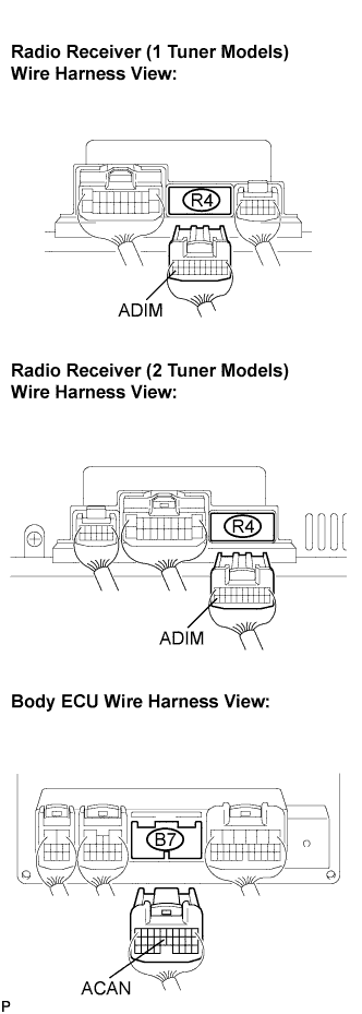 |
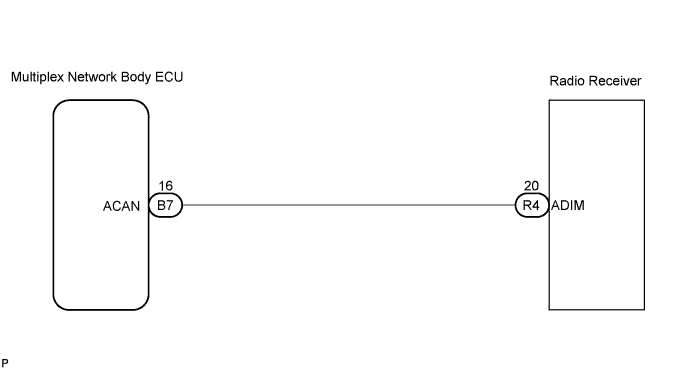
Disconnect the radio receiver connector R4 and multiplex network body ECU connector B7.
Measure the resistance according to the values in the table below.
| Tester connection | Condition | Specified condition |
| ADIM - ACAN | Always | Below 1 Ω |
| ADIM - Body ground | Always | 10 kΩ or higher |
|
| ||||
| OK | |
| 2.INSPECT RADIO RECEIVER |
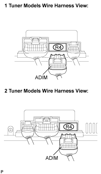 |
Connect the multiplex network body ECU connector.
Turn the ignition switch to the ON position.
Turn the light control switch to the TAIL or HEAD position.
Measure the voltage according to the value(s) in the table below.
| Tester connection | Condition | Specified condition |
| ADIM - Body ground | Light control switch in TAIL or HEAD | 10 to 14 V |
|
| ||||
| OK | ||
| ||
