METER / GAUGE SYSTEM > TERMINALS OF ECU |
| Combination Meter Assembly |
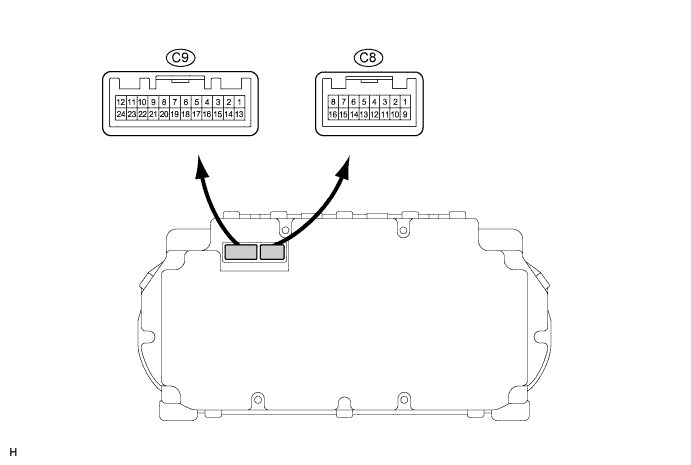
| Symbols (Terminal No.) | Wiring Color | Terminal Description | Condition | Specified Condition |
| POWER GND (C8-1) - Body ground | L-B - Body ground | Ground (Power ground) | Always | Below 1 V |
| ILL- (C8-2) - Body ground | L - Body ground | Illumination signal | Turn the ignition switch to the ON position, combination switch TAIL | Below 1 V → 10 to 16 V |
| CHECK ENGINE (C8-4) - Body ground | BR - Body ground | Check engine signal | Turn the ignition switch to the ON position, check engine warning light OFF → ON | 10 to 16 V → Below 1.5 V |
| MPX+ (C8-5) - Body ground | Y - Body ground | Communication line | - | - |
| SPEED SIGNAL (4P) (C8-6) - Body ground | LG - Body ground | Speed signal (Output) | Turn the ignition switch to the ON position, turn the wheel slowly | Pulse generation (See waveform 1) |
| IG2 (C8-8) - Body ground | GR - Body ground | Battery | Ignition switch OFF → ON | Below 1 V → 10 to 16 V |
| TURN R (C8-13) - Body ground | P - Body ground | Turn signal flasher | Turn the ignition switch to the ON position, turn signal RH indicator light OFF → ON | Below 1 V → 10 to 16 V |
| TURN L (C8-14) - Body ground | B - Body ground | Turn signal flasher | Turn the ignition switch to the ON position, turn signal LH indicator light OFF → ON | Below 1 V → 10 to 16 V |
| ECU +B (C8-15) - Body ground | SB - Body ground | Battery | Always | 10 to 16 V |
| DOME +B (C8-16) - Body ground | O - Body ground | Battery | Always | 10 to 16 V |
| SIGNAL GND (C9-1) - Body ground | W-B - Body ground | Ground (Signal ground) | Always | Below 1 V |
| FE (C9-2) - Body ground | P - Body ground | Ground (Fuel ground) | Always | Below 1 V |
| MPX- (C9-4) - Body ground | B - Body ground | Communication line | - | - |
| POWER METER (C9-8) - Body ground | W - Body ground | Power meter signal | Turn the Ignition switch to the off → ON position | Pulse generation (See waveform 2) |
| MULTI MODE SW (C9-9) - Body ground | Y - Body ground | Multi mode switch signal | Turn the ignition switch to the ON position, multi mode switch OFF → ON | 4 to 6V → Below 1 V |
| H-LP LEVEL (C9-10) (*1) - Body ground | B - Body ground | Headlight beam level control signal | Turn the ignition switch to the ON position, leveling indicator light OFF → ON | 10 to 16 V → Below 1 V |
| RE (C9-13) - Body ground | W - Body ground | Ground (Rheostat ground) | Always | Below 1 V |
| RV (C9-14) - Body ground | O - Body ground | Light control rheostat signal | Turn the ignition switch to the ON position, rheostat knob position MIN → MAX | Below 1 V → 4 to 6 V |
| RL (C9-15) - Body ground | B - Body ground | Light control rheostat signal | Turn the ignition switch to the ON position | 4 to 6 V |
| TCAN SW (C9-16) - Body ground | Y - Body ground | Tail cancel switch signal | Turn the ignition switch to the ON position, tail cancel switch OFF → ON | 4 to 6 V → Below 1 V |
| RSET (C9-17) - Body ground | L - Body ground | ODO/TRIP switch signal | Turn the ignition switch to the ON position, ODO/TRIP switch OFF → ON | 4 to 6 V → Below 1 V |
| SPEED SIGNAL (C9-18) - Body ground | BR - Body ground | Speed signal (Input) | Turn the ignition switch to the ON position, turn the wheel slowly | Pulse generation (See waveform 2) |
| FUEL SENDER (C9-19) - Body ground | V - Body ground | Fuel level signal | Turn the ignition switch to the ON position, fuel level MIN → MAX | 4 to 9 V → Below 2V |
| P-SEAT (C9-20) - Body ground | GR - Body ground | Passenger seat condition signal | Sits on the passenger seat and turn the ignition switch to the off → ON position | 10 to 16 V → Below 1 V |
| OIL LEVEL (C9-21) - Body ground | BR - Body ground | Engine oil level signal | Turn the ignition switch to the ON position, low engine oil level warning comes on. | Below 1 V → 10 to 16 V |
| P SEAT BELT (C9-22) (*2) - Body ground | P - Body ground | Passenger side seat belt signal | Turn the ignition switch to the ON position, passenger seat belt warning light OFF → blinks | 10 to 16 V → Below 1 V |
| WASHER LEVEL (C9-24) - Body ground | LG - Body ground | Washer level indicator light signal | Turn the ignition switch to the ON position, washer level indicator light OFF → ON | 10 to 16 V → Below 1 V |
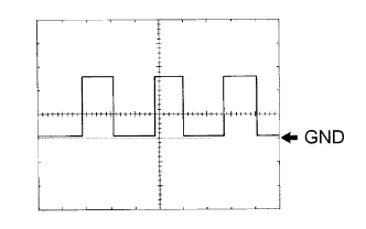 |
Waveform 1 (Reference): Using an oscilloscope:
| Item | Condition |
| Tool setting | 5 V/DIV., 20 ms/DIV. |
| Vehicle condition | Driving at approx. 20 km/h (12 mph) |
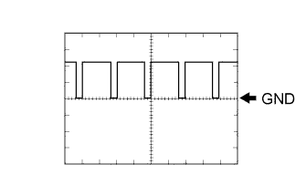 |
Waveform 2 (Reference): Using an oscilloscope:
| Item | Condition |
| Tool setting | 1 V/DIV., 2 μsec/DIV. |
| Vehicle condition | Turn the ignition switch to the ON position. |
| Integration Control & Panel Assembly (w/o Navigation System) |

| Symbols (Terminal No.) | Wiring Color | Terminal Description | Condition | Specified Condition |
| +B (C4-1) - Body ground | O - Body ground | Battery | Always | 10 to 14 V |
| ACC (C4-2) - Body ground | GR - Body ground | Ignition Switch Signal | Turn the ignition switch to the off → ON position | Below 1 V → 10 to 14 V |
| LP (C4-4) - Body ground | P - Body ground | Security Indicator Signal | Turn the ignition switch to the ON position, security indicator light ON → OFF | Below 1 V → 10 to 14 V |
| MPX- (C4-5) | L - Body ground | Multiplex Communication Signal | - | - |
| P-AB (C4-6) - Body ground | BR - Body ground | Passenger Airbag Off Indicator Light Signal | Turn the ignition switch to the ON position, passenger airbag off indicator light OFF → ON | Below 1 V → 10 to 14 V |
| GND (C4-7) - Body ground | W-B - Body ground | Ground | Always | Below 1 V |
| ILL+ (C4-8) - Body ground | G - Body ground | Illumination Signal | Combination switch OFF → Head | Below 1 V → 10 to 14 V |
| IG+ (C4-9) - Body ground | LG - Body ground | Ignition Switch Signal | Ignition switch signal | Below 1 V → 10 to 14 V |
| F (C4-11) - Body ground | V - Body ground | Turn Light Signal | Turn indicator light OFF → ON | Below 1 V → 10 to 14 V |
| MPX - (C4-12) | R - Body ground | Multiplex Communication Signal | - | - |
| PAON (C4-13) - Body ground | Y - Body ground | Passenger Airbag On Indicator Light Signal | Turn the ignition switch to the ON position, passenger airbag on indicator light OFF → ON | Below 1 V → 10 to 14 V |
| ILL- (C4-14) - Body ground | W - Body ground | Illumination Signal | Turn the ignition switch to the ON position, combination switch Head, and light control rheostat position MIN. → MAX. | Pulse generation (See waveform) |
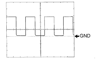 |
Waveform (Reference): Using an oscilloscope:
| Item | Condition |
| Tool setting | 5 V/DIV., 2 ms/DIV. |
| Vehicle condition | Turn the ignition switch to the ON position, light control rheostat is in the MID position. |
| Multi-Display Assembly (w/ Navigation System) |

| Symbols (Terminal No.) | Wiring Color | Terminal Description | Condition | Specified Condition |
| GND (M5-3) - Body ground | W-B - Body ground | Ground | Always | Below 1 V |
| IG (M5-10) - Body ground | LG - Body ground | Ignition Switch Signal | Turn the ignition switch to the off → ON position | Below 1 V → 10 to 16 V |
| ACC (M5-11) - Body ground | GR - Body ground | Ignition Switch Signal | Turn the ignition switch to the off → ON position | Below 1 V → 10 to 16 V |
| +B (M5-12) - Body ground | G - Body ground | Battery | Always | 10 to 16 V |
| PBEW (M5-21) - Body ground | O - Body ground | Passenger Seat Belt Indicator Light Signal | Turn the ignition switch to the ON position, passenger seat belt indicator light OFF → ON | Pulse generation (See waveform) |
|
Waveform (Reference): Using an oscilloscope:
| Item | Condition |
| Tool setting | 5 V/DIV., 200 ms/DIV. |
| Vehicle condition | Turn the ignition switch to the ON position, p-belt indicator light blinks. |
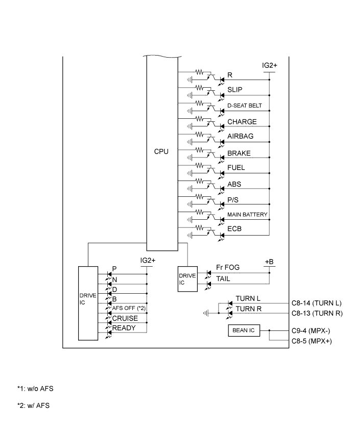
| COMBINATION METER INNER CIRCUIT |
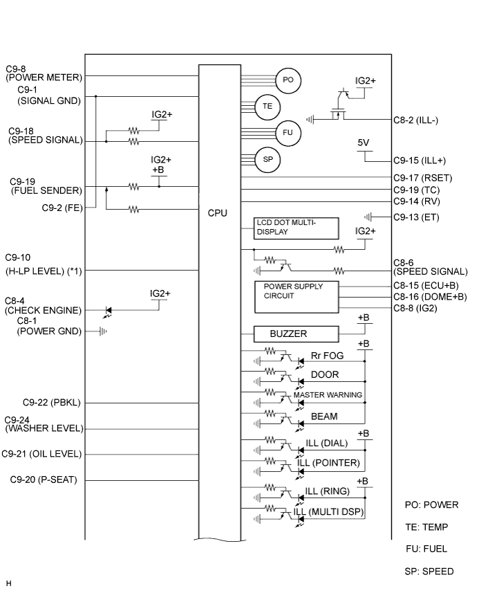
| Terminal No. | Wire harness side | |
| C8 | 1 | Ground (Power Ground) |
| 2 | Each part that uses illumination signal (Audio Controller, Integration Control & Panel Assembly, Console Box, Multi-display) | |
| 3 | - | |
| 4 | Hybrid Vehicle Control ECU (Check Engine) | |
| 5 | Multiplex Communication Line, Integration Control & Panel Assembly (*1) | |
| 6 | Each part that uses speed signal | |
| 7 | - | |
| 8 | Gauge Fuse | |
| 9 | - | |
| 10 | - | |
| 11 | - | |
| 12 | - | |
| 13 | Turn Signal Flasher R | |
| 14 | Turn Signal Flasher L | |
| 15 | ECU-B Fuse | |
| 16 | DOME Fuse | |
| C9 | 1 | Ground (Signal Ground) |
| 2 | Ground (Fuel Ground) | |
| 3 | - | |
| 4 | Multiplex Communication Line | |
| 5 | - | |
| 6 | - | |
| 7 | - | |
| 8 | Hybrid Vehicle Control ECU (Power Meter) | |
| 9 | Steering Pad Switch (DISP) | |
| 10 | Headlight Beam Level Control ECU (*2) | |
| 11 | - | |
| 12 | - | |
| 13 | Light Control Rheostat | |
| 14 | Light Control Rheostat | |
| 15 | Light Control Rheostat | |
| 16 | Light Control Rheostat (Tail Cancel Switch) | |
| 17 | Light Control Rheostat (ODO/TRIP Switch) | |
| 18 | ABS & Traction Actuator Assembly | |
| 19 | Fuel Sender Gauge Assembly | |
| 20 | Occupant Classification Sensor | |
| 21 | Engine Oil Level Sensor | |
| 22 | Multi-display (*3) | |
| 23 | - | |
| 24 | Washer Level Warning Switch | |
