OIL PUMP > REMOVAL |
| 1. REMOVE ENGINE ASSEMBLY WITH TRANSAXLE |
| 2. REMOVE ENGINE WIRE |
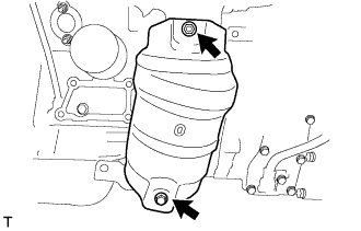
| 3. REMOVE EXHAUST MANIFOLD HEAT INSULATOR NO.1 |
 |
Remove the 3 bolts and exhaust manifold heat insulator No.1.
| 4. REMOVE MANIFOLD STAY |
Remove the 2 bolts and manifold stay.
| 5. REMOVE EXHAUST MANIFOLD SUB-ASSEMBLY RH |
Disconnect the heated oxygen sensor connector.
 |
Using several steps, loosen and remove the 6 nuts in the sequence shown in the illustration.
Remove the exhaust manifold RH and the gasket from the cylinder head RH.
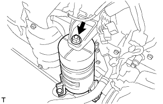
| 6. REMOVE HV TRANSAXLE MASS DAMPER |
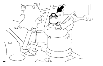 |
Remove the bolt and transaxle mass damper.
| 7. REMOVE FRONT FRAME ASSEMBLY |
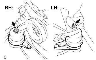 |
Remove the 2 nuts and separate the engine mounting insulators RH and LH.
 |
Remove the nut and separate engine mounting insulator FR.
 |
Remove the 2 bolts and separate the engine mounting insulator RR.
| 8. REMOVE FRONT DRIVE SHAFT ASSEMBLY LH |
 |
Using SST, remove the front drive shaft assembly LH.
| 9. REMOVE FRONT DRIVE SHAFT ASSEMBLY RH |
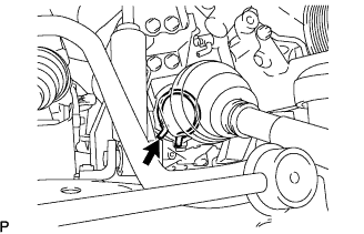 |
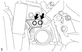
Using pliers, remove the bearing bracket hole snap ring.
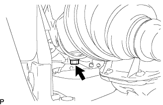 |
Remove the bolt from the drive shaft bearing bracket.
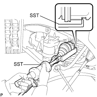
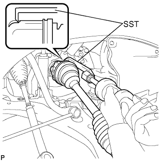 |
Using SST, remove the front drive shaft assembly RH.
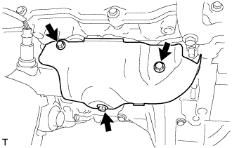
| 10. REMOVE FLYWHEEL HOUSING UNDER COVER |
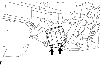 |
Remove the 2 bolts and flywheel housing under cover.
| 11. REMOVE ENGINE MOUNTING BRACKET FRONT |
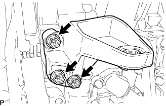 |
Remove the 3 bolts and engine mounting bracket.
| 12. REMOVE HYBRID VEHICLE TRANSAXLE ASSEMBLY |
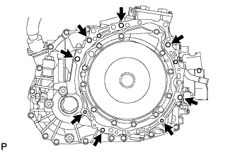 |
Remove the 8 bolts.
Separate and remove the hybrid vehicle transaxle.
| 13. REMOVE TRANSMISSION INPUT DAMPER ASSEMBLY |
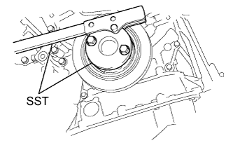 |
Using SST, hold the crankshaft.
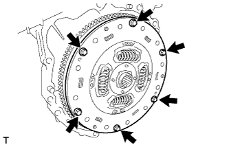 |
Remove the 6 bolts and transmission input damper from the flywheel.
| 14. REMOVE FLYWHEEL SUB-ASSEMBLY |
|
Using SST, hold the crankshaft.
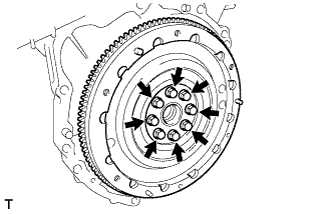 |
Remove the 8 bolts and flywheel.
| 15. INSTALL ENGINE STAND |
| 16. REMOVE MANIFOLD CONVERTER INSULATOR NO.3 |
 |
Remove the bolt, nut and manifold converter insulator No.3.
| 17. REMOVE EXHAUST MANIFOLD HEAT INSULATOR NO.2 |
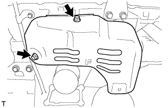 |
Remove the 2 bolts and manifold heat insulator No.2.
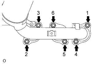
| 18. REMOVE EXHAUST MANIFOLD CONVERTER SUB-ASSEMBLY NO.2 |
Disconnect the heated oxygen sensor connector.
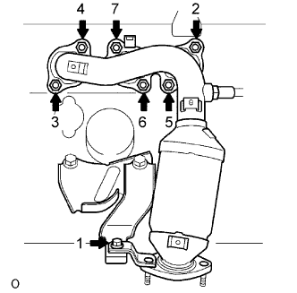 |
Using several steps, loosen and remove the 6 nuts and bolt in the sequence shown in the illustration.
Remove the exhaust manifold converter No.2 and the gasket from the cylinder head LH.
| 19. REMOVE MANIFOLD STAY NO.2 |
Remove the 2 bolts and manifold stay No.2.
| 20. REMOVE ENGINE MOUNTING BRACKET RH |
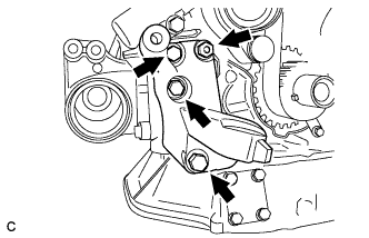 |
Remove the 3 bolts and engine mounting bracket RH.
| 21. REMOVE ENGINE MOUNTING STAY BRACKET |
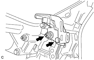 |
Remove the bolt, nut and engine mounting stay bracket.
| 22. REMOVE COMPRESSOR MOUNTING BRACKET NO.1 |
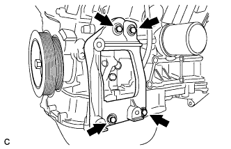 |
Remove the 4 bolts and compressor mounting bracket.
| 23. REMOVE CRANKSHAFT PULLEY |
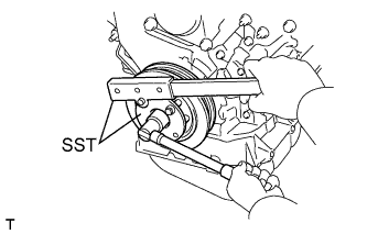 |
Using SST, loosen the pulley bolt.
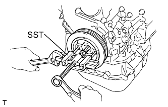 |
Using SST and the pulley bolt, remove the pulley.
| 24. REMOVE TIMING BELT NO.1 COVER |
Remove the 4 bolts and the timing belt cover No.1.
| 25. REMOVE TIMING BELT NO.2 COVER |
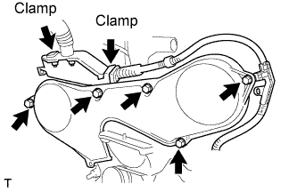 |
Disconnect the engine wire protector clamps from the timing belt No.2 cover.
Remove the 5 bolts and the timing belt cover.
| 26. REMOVE ENGINE MOUNTING BRACKET RH |
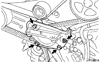 |
Remove the 2 bolts, 2 nuts and engine mounting bracket RH.
| 27. REMOVE TIMING BELT GUIDE NO.2 |
| 28. REMOVE TIMING BELT |
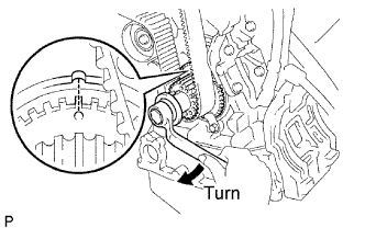 |
Set No.1 cylinder to TDC/compression.
Temporarily install the crankshaft pulley bolt and washer to the crankshaft.
Turn the crankshaft clockwise, and align the timing mark of the crankshaft timing pulley with the oil pump body.
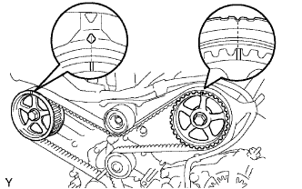 |
Check that the timing marks of the camshaft timing pulleys and No.3 timing belt cover are aligned.
If not, turn the crankshaft 1 revolution (360°).
Remove the crankshaft pulley bolt.
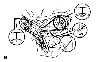 |
If reusing the timing belt, check that there are 3 installation marks on the timing belt as shown in the illustration.
If the installation marks have disappeared, put new installation marks on the timing belt before removing.
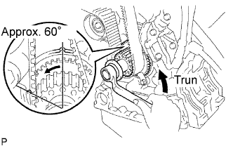 |
Set No.1 cylinder to approximately 60° BTDC/compression.
Turn the crankshaft counterclockwise by approximately 60°.
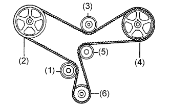 |
Remove the timing belt tensioner.
| 1st | No.1 idler pulley |
| 2nd | RH camshaft timing pulley |
| 3rd | No.2 idler pulley |
| 4th | LH camshaft timing pulley |
| 5th | Water pump pulley |
| 6th | Crankshaft timing pulley |
| 29. REMOVE TIMING BELT IDLER SUB-ASSEMBLY NO.1 |
Using a socket hexagon wrench 10 mm, remove the pivot bolt, timing belt idler No.1 and distributor drive gear plate washer.
| 30. REMOVE CRANKSHAFT TIMING PULLEY |
Remove the bolt and the timing belt plate.
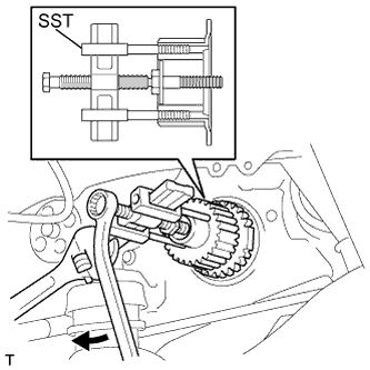 |
Install the pulley bolt to the crankshaft.
Using SST, remove the crankshaft timing pulley.
| 31. REMOVE OIL LEVEL GAGE SUB-ASSEMBLY |
Remove the oil level gage sub-assembly from the oil level gage guide.
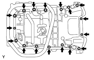
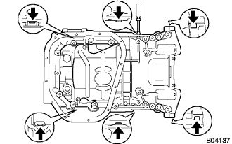
| 32. REMOVE OIL PAN SUB-ASSEMBLY NO.2 |
 |
Remove the 10 bolts and 2 nuts.
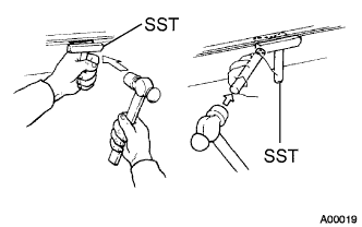 |
Insert the blade of SST between oil pan No.1 and oil pan No.2, cut off the sealer and remove the oil pan No.2.
| 33. REMOVE OIL STRAINER SUB-ASSEMBLY |
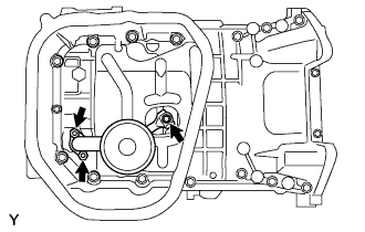 |
Remove the bolt and 2 nuts, and remove the oil strainer and the gasket.
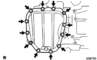
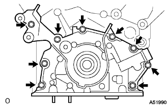
| 34. REMOVE OIL PAN SUB-ASSEMBLY |
 |
Loosen and remove the 17 bolts uniformly.
 |
Using a screwdriver, remove the oil pan by prying between the cylinder block and the oil pan.
| 35. REMOVE CRANK POSITION SENSOR |
Disconnect the crankshaft position sensor connector.
Remove the bolt and the crankshaft position sensor.
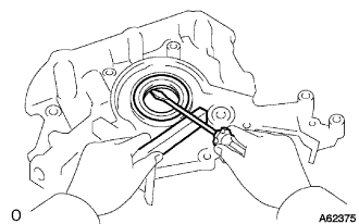
| 36. REMOVE OIL PUMP ASSEMBLY |
 |
Remove the 9 bolts.
Using a screwdriver, remove the oil pump by prying between the oil pump and the main bearing cap.
 |
Remove the O-ring.
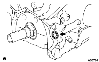
| 37. REMOVE OIL PUMP SEAL |
 |
Using a screwdriver, pry out the oil seal.
