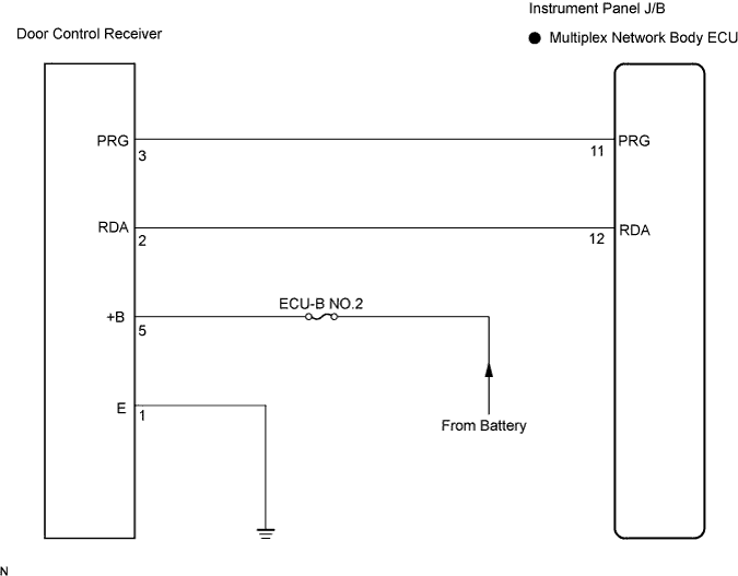
DTC B1242/42 Wireless Door Lock Tuner Circuit Malfunction |
| DTC No. | DTC Detection Condition | Suspected Area |
| B1242/42 | In the diagnostic mode, the applicable RDA signal cannot be received within 1 second after PRG signal has been output from the body ECU. |
|
| 1.CHECK HARNESS AND CONNECTOR (MULTIPLEX NETWORK BODY ECU TO DOOR CONTROL RECEIVER) |
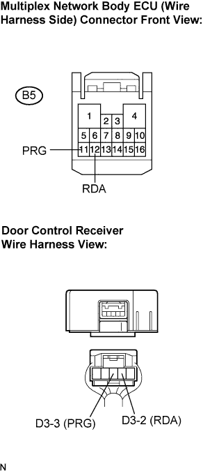 |
Disconnect the multiplex network body ECU (B5) connector and door control receiver connector.
Measure the resistance according to the value(s) in the table below.
| Tester connection | Condition | Specified condition |
| B5-11 (PRG) - D3-3 (PRG) | Always | Below 1 Ω |
| B5-11 (PRG) - Body ground | Always | 10 kΩ or higher |
| B5-12 (RDA) - D3-2 (RDA) | Always | Below 1 Ω |
| B5-12 (RDA) - Body ground | Always | 10 kΩ or higher |
|
| ||||
| OK | |
| 2.INSPECT DOOR CONTROL RECEIVER (+B TERMINAL) |
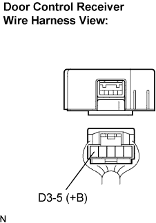 |
Measure the voltage according to the value(s) in the table below.
| Tester connection | Condition | Specified condition |
| D3-5 (+B) - Body ground | Always | 10 to 14 V |
|
| ||||
| OK | |
| 3.INSPECT DOOR CONTROL RECEIVER (E TERMINAL) |
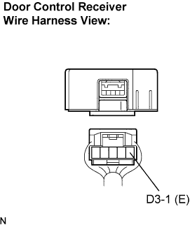 |
Measure the resistance according to the value(s) in the table below.
| Tester connection | Condition | Specified condition |
| D3-1 (E) - Body ground | Always | Below 1 Ω |
|
| ||||
| OK | |
| 4.REPLACE DOOR CONTROL RECEIVER |
Reconnect the multiplex network body ECU connector.
Replace the door control receiver (Click here).
Perform the REGISTRATION procedures (Click here).
| NEXT | |
| 5.RECHECK DTC |
Clear the DTC (Click here).
Check if the same DTC is detected (Click here).
| Condition | Proceed to |
| DTC (B1242/42) is output | A |
| DTC (B1242/42) is not output | B |
|
| ||||
| A | ||
| ||
