EMISSION CONTROL SYSTEM > ON-VEHICLE INSPECTION |
| 1. INSPECT AIR FUEL RATIO COMPENSATION SYSTEM |
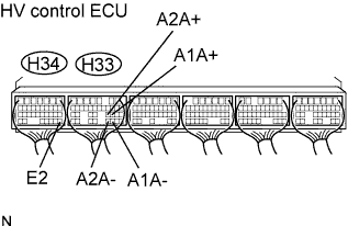 |
Measure the voltage between the terminals of the hybrid vehicle control ECU connectors.
| Tester Connection | Condition | Specified Condition |
| H33 - 22 (A1A+) to H34 - 28 (E2) | Ignition switch ON | 3.3 V |
| H33 - 30 (A1A-) to H34 - 28 (E2) | Ignition switch ON | 3.0 V |
| H33 - 23 (A2A+) to H34 - 28 (E2) | Ignition switch ON | 3.3 V |
| H33 - 31 (A2A-) to H34 - 28 (E2) | Ignition switch ON | 3.0 V |
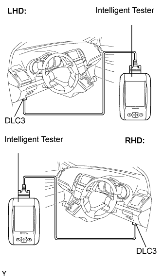
Connect the intelligent tester to the DLC3.
Select "Data List". Then select "AFS B1 S1", "AFS B2 S1", "O2S B1 S2" and "O2S B2 S2" to display the monitors.
Warm up the air fuel ratio sensor with the engine speed at 2,500 rpm for approximately 2 minutes.
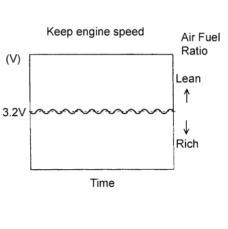 |
Maintain the engine speed at 2,500 rpm and confirm that the displays of "AFS B1 S1" and "AFS B2 S1" are as shown in the illustration.
Confirm that the display of "O2S B1 S2" and "O2S B2 S2" changes between 0 and 1 V with the engine speed at 2,500 rpm.
| 2. INSPECT FUEL CUT OFF / RESTART RPM |
Increase the engine speed to at least 3,500 rpm.
Use a sound scope to check for injector operating sounds.
Check that when the throttle lever is released, injector operation sound stops momentarily (at 2,500 rpm) and then resumes (at 1,200 rpm).
| Item | Specified Condition |
| Fuel cut off rpm | 2,500 rpm |
| Fuel injector restart rpm | 1,400 rpm |
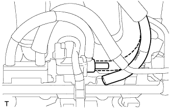
| 3. VISUALLY INSPECT HOSE, CONNECTIONS AND GASKETS |
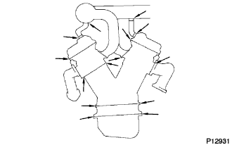 |
Check for cracks, leaks or damage.
| 4. INSPECT EVAP SYSTEM LINE |
PERFORM ACTIVE TEST
 |
Put the engine in inspection mode (Click here)
Connect the intelligent tester to the DLC3.
Start the engine.
Turn the tester ON.
 |
Disconnect the fuel vapor feed hose.
Enter the following menus : Power train / Engine / Active Test.
Check that a vacuum occurs at the VSV port.
Finish Active test, then connect the vacuum hose.
READ DATA LIST
|
Put the engine in inspection mode (Click here)
Warm up the engine.
Turn the ignition switch OFF.
Connect the intelligent tester to the DLC3.
Start the engine.
Turn the tester ON.
Enter the following menus : Power train / Engine / Data List.
Check the values by referring to the table below.
| Intelligent Tester Display | Measurement: Range (Display) | Diagnostic Note |
| EVAP Purge VSV EVAP (Purge) VSV | VSV status for EVAP control: ON or OFF | Active Test support data |
