FRONT POWER SEAT CONTROL SYSTEM > Power Seat Motor Circuit |
| 1.PERFORM ACTIVE TEST BY INTELLIGENT TESTER |
Connect the intelligent tester to the DLC3.
Turn the ignition switch on.
Perform the ACTIVE TEST by following the directions on the tester screen.
| Item | Test Details | Diagnostic Note |
| Seat Reclining | Test detail: reclining operation FRONT/REAR Vehicle condition: stopped | - |
| Front Vertical Operation | Test detail: front vertical operation UP/DOWN Vehicle condition: stopped | - |
| Lifter Operation | Test detail: lifter operation UP/DOWN Vehicle condition: stopped | - |
| Seat Slide Operation | Test detail: sliding operation UP/DOWN Vehicle condition: stopped | - |
|
| ||||
| OK | ||
| ||
| 2.INSPECT FRONT SEAT ADJUSTER SUB-ASSEMBLY (POWER SEAT MOTOR) |
Inspect the power seat motor (Click here).
|
| ||||
| OK | |
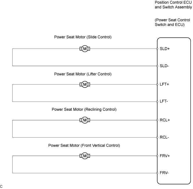
| 3.CHECK HARNESS AND CONNECTOR (POSITION CONTROL ECU AND SWITCH ASSEMBLY - POWER SEAT MOTOR) |
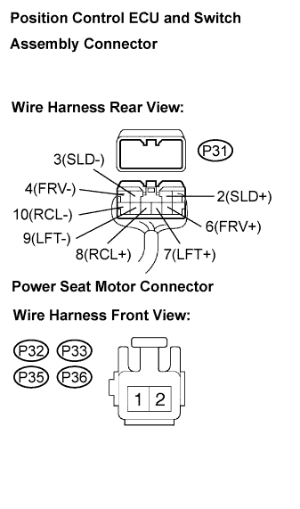 |
Disconnect the position control ECU and switch assembly connector and power seat motor connectors.
Measure the resistance according to the value(s) in the table below.
| Tester Connection | Condition | Specified Condition |
| P31-2(SLD+) - P36-1 | Always | Below 1 Ω |
| P31-3(SLD-) - P36-2 | Always | Below 1 Ω |
| P31-4(FRV-) - P32-2 | Always | Below 1 Ω |
| P31-6(FRV+) - P32-1 | Always | Below 1 Ω |
| P31-7(LFT+) - P33-2 | Always | Below 1 Ω |
| P31-9(LFT-) - P33-1 | Always | Below 1 Ω |
| P31-8(RCL+) - P35-2 | Always | Below 1 Ω |
| P31-10(RCL-) - P35-1 | Always | Below 1 Ω |
| P31-2(SLD+) - Body ground | Always | 10 kΩ or higher |
| P31-3(SLD-) - Body ground | Always | 10 kΩ or higher |
| P31-4(FRV-) - Body ground | Always | 10 kΩ or higher |
| P31-6(FRV+) - Body ground | Always | 10 kΩ or higher |
| P31-7(LFT+) - Body ground | Always | 10 kΩ or higher |
| P31-9(LFT-) - Body ground | Always | 10 kΩ or higher |
| P31-8(RCL+) - Body ground | Always | 10 kΩ or higher |
| P31-10(RCL-) - Body ground | Always | 10 kΩ or higher |
| Tester Connection | Condition | Specified Condition |
| P31-2(SLD+) - P36-2 | Always | Below 1 Ω |
| P31-3(SLD-) - P36-1 | Always | Below 1 Ω |
| P31-4(FRV-) - P32-1 | Always | Below 1 Ω |
| P31-6(FRV+) - P32-2 | Always | Below 1 Ω |
| P31-7(LFT+) - P33-1 | Always | Below 1 Ω |
| P31-9(LFT-) - P33-2 | Always | Below 1 Ω |
| P31-8(RCL+) - P35-2 | Always | Below 1 Ω |
| P31-10(RCL-) - P35-1 | Always | Below 1 Ω |
| P31-2(SLD+) - Body ground | Always | 10 kΩ or higher |
| P31-3(SLD-) - Body ground | Always | 10 kΩ or higher |
| P31-4(FRV-) - Body ground | Always | 10 kΩ or higher |
| P31-6(FRV+) - Body ground | Always | 10 kΩ or higher |
| P31-7(LFT+) - Body ground | Always | 10 kΩ or higher |
| P31-9(LFT-) - Body ground | Always | 10 kΩ or higher |
| P31-8(RCL+) - Body ground | Always | 10 kΩ or higher |
| P31-10(RCL-) - Body ground | Always | 10 kΩ or higher |
|
| ||||
| OK | ||
| ||
