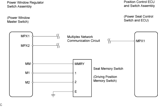
FRONT POWER SEAT CONTROL SYSTEM > Driving Position Memory Switch Circuit (w/ Memory) |
| 1.READ VALUE OF INTELLIGENT TESTER |
Connect the intelligent tester to the DLC3.
Turn the ignition switch on.
Read the DATA LIST.
| Item | Measurement Item/Range (Display) | Normal Condition | Diagnostic Note |
| M2 Switch | Seat memory M2 switch signal/ ON or OFF | ON: Seat memory M2 switch is ON OFF: Seat memory M2 switch is OFF | - |
| M1 Switch | Seat memory M1 switch signal/ ON or OFF | ON: Seat memory M1 switch is ON OFF: Seat memory M1 switch is OFF | - |
| SET Switch | Seat memory set switch signal/ ON or OFF | ON: Seat memory set switch is ON OFF: Seat memory set switch is OFF | - |
|
| ||||
| OK | ||
| ||
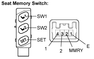
| 2.INSPECT SEAT MEMORY SWITCH (DRIVING POSITION MEMORY SWITCH) |
Remove the seat memory switch.
 |
Measure the resistance according to the value(s) in the table below.
| Tester Connection | Switch Position | Specified Condition |
| 1(E) - 2(MMRY) | SET switch ON (pushed) | Below 1 Ω |
| 1(E) - 2(MMRY) | SET switch OFF (not pushed) | 10 kΩ or higher |
| 1(E) - 4(1) | SW1 switch ON (pushed) | Below 1 Ω |
| 1(E) - 4(1) | SW1 switch OFF (not pushed) | 10 kΩ or higher |
| 1(E) - 3(2) | SW2 switch ON (pushed) | Below 1 Ω |
| 1(E) - 3(2) | SW2 switch OFF (not pushed) | 10 kΩ or higher |
|
| ||||
| OK | |
| 3.CHECK HARNESS AND CONNECTOR (SEAT MEMORY SWITCH CIRCUIT) |
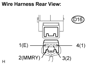 |
Measure the voltage according to the value(s) in the table below.
| Tester Connection | Switch Position | Specified Condition |
| D16-2(MMRY) - D16-1(E) | Ignition switch on | 10 to 14 V |
| D16-3(2) - D16-1(E) | Ignition switch on | 10 to 14 V |
| D16-4(1) - D16-1(E) | Ignition switch on | 10 to 14 V |
|
| ||||
| OK | ||
| ||
| 4.CHECK HARNESS AND CONNECTOR (POWER WINDOW REGULATOR SWITCH ASSEMBLY - SEAT MEMORY SWITCH) |
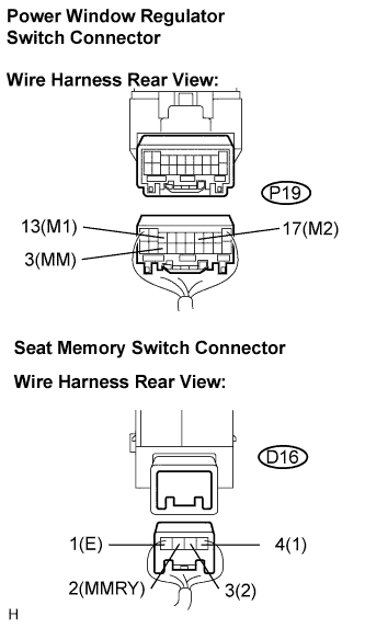 |
Disconnect the power window regulator switch assembly connector.
Measure the resistance according to the value(s) in the table below.
| Tester Connection | Switch Position | Specified Condition |
| D16-1(E) - Body ground | Always | Below 1 Ω |
| D16-2(MMRY) - P19-3(MM) | Always | Below 1 Ω |
| D16-3(2) - P19-17(M2) | Always | Below 1 Ω |
| D16-4(1) - P19-13(M1) | Always | Below 1 Ω |
| D16-2(MMRY) - Body ground | Always | 10 kΩ or higher |
| D16-3(2) - Body ground | Always | 10 kΩ or higher |
| D16-4(1) - Body ground | Always | 10 kΩ or higher |
|
| ||||
| OK | ||
| ||
