POWER WINDOW CONTROL SYSTEM > TERMINALS OF ECU |
| MULTIPLEX NETWORK MASTER SWITCH |

Disconnect the P19 switch connector.
Measure the voltage and resistance of each terminal according to the value(s) in the table below.
| Symbols (Terminal No.) | Wiring Color | Terminal Description | Condition | Specified Condition |
| GND (P19-2) - Body ground | W-B - Body ground | Ground | Constant | Below 1 Ω |
| Symbols (Terminal No.) | Wiring Color | Terminal Description | Condition | Specified Condition |
| BDR (P19-10) - GND (P19-2) | G - W-B | +B power supply | Constant | 10 to 14 V |
| CPUB (P19-9) - GND (P19-2) | L-B - W-B | +B power supply | Constant | 10 to 14 V |
| SIG (P19-20) - GND (P19-2) | BR - W-B | Ignition power supply | Ignition switch OFF → ON | 0 V → 10 to 14 V |
Reconnect the P19 switch connector and reset the power window motor.
Measure the voltage according to the value(s) in the table below.
| Symbols (Terminal No.) | Wiring Color | Terminal Description | Condition | Specified Condition |
| UP (P19-1) - GND (P19-2) | GR - W-B | Power window motor UP output | Ignition switch ON, Driver side power window switch OFF → UP (Manual operation) | 0 V → 10 to 14 V |
| UP (P19-1) - GND (P19-2) | GR - W-B | Power window motor UP output | Ignition switch ON, Driver side power window fully open → Driver side power window switch UP (AUTO operation) → Driver side power window fully closed | 0 V → 10 to 14 V → 0 V |
| DN (P19-11) - GND (P19-2) | B - W-B | Power window motor DOWN output | Ignition switch ON, Driver side power window switch OFF → DOWN (Manual operation) | 10 to 14 V → 0 V |
| DN (P19-11) - GND (P19-2) | B - W-B | Power window motor DOWN output | Ignition switch ON, Driver side power window fully closed → Driver side power window switch DOWN (AUTO operation) → Driver side power window fully open | 10 to 14 V → 0 V |
| PWS (P19-6) - GND (P22-2) | O - W-B | Power window lock switch output | Ignition switch ON, Power window lock switch UNLOCK → LOCK | 10 to 14 V → 0 V |
| VCC (P19-19) - GND (P19-2) | O - W-B | Power window motor power source | Constant | 10 to 14 V |
| CHECK MULTIPLEX NETWORK SWITCH (FRONT PASSENGER SIDE) |

Disconnect the P15 (P16) switch connector.
Measure the voltage and resistance according to the value(s) in the table below.
| Symbols (Terminal No.) | Wiring Color | Terminal Description | Condition | Specified Condition |
| GND (7) - Body ground | W-B - Body ground | Ground | Constant | Below 1 Ω |
| Symbols (Terminal No.) | Wiring Color | Terminal Description | Condition | Specified Condition |
| BDR (12) - GND (7) | G - W-B | +B power supply | Constant | 10 to 14 V |
Reconnect the P15 (P16) switch connector and reset power window motor.
Measure the voltage according to the value(s) in the table below.
| Symbols (Terminal No.) | Wiring Color | Terminal Description | Condition | Specified Condition |
| UP (6) - GND (7) | GR - W-B | Power window motor UP output | Ignition switch ON, Regulator switch OFF → UP (Manual operation) | 0 V → 10 to 14 V |
| UP (6) - GND (7) | GR - W-B | Power window motor UP output | Ignition switch ON, Front passenger side power window fully open → Regulator switch UP (AUTO operation) → Front passenger side power window fully closed | 0 V → 10 to 14 V → 0 V |
| DN (1) - GND (7) | B - W-B | Power window motor DOWN output | Ignition switch ON, Regulator switch OFF → DOWN (Manual operation) | 10 to 14 V → 0 V |
| DN (1) - GND (7) | B - W-B | Power window motor DOWN output | Ignition switch ON, Front passenger side power window fully closed → Regulator switch DOWN (AUTO operation) → Front passenger side power window fully open | 10 to 14 V → 0 V |
| PCT (11) - GND (7) | O - W-B | Power window lock switch output | Ignition switch ON, Power window lock switch UNLOCK → LOCK | 10 to 14 V → 0 V |
| VCC (5) - SGND (8) | LG - R | Power window motor power source | Constant | 10 to 14 V |
| CHECK MULTIPLEX NETWORK SWITCH (REAR LH) |

Disconnect the P17 switch connector.
Measure the voltage and resistance according to the value(s) in the table below.
| Symbols (Terminal No.) | Wiring Color | Terminal Description | Condition | Specified Condition |
| GND (P17-7) - Body ground | W-B - Body ground | Ground | Constant | Below 1 Ω |
| SEL2 (P17-10) - GND (P20-7) | W-B - W-B | Terminal for identification of rear LH switch | Constant | Below 1 Ω |
| Symbols (Terminal No.) | Wiring Color | Terminal Description | Condition | Specified Condition |
| BDR (P17-12) - GND (P17-7) | LG - W-B | +B power supply | Constant | 10 to 14 V |
Reconnect the P17 switch connector and reset the power window motor.
Measure the voltage according to the value(s) in the table below.
| Symbols (Terminal No.) | Wiring Color | Terminal Description | Condition | Specified Condition |
| UP (P17-6) - GND (P17-7) | V - W-B | Power window motor UP output | Ignition switch ON, Regulator switch OFF → UP (Manual operation) | 0 V → 10 to 14 V |
| UP (P17-6) - GND (P17-7) | V - W-B | Power window motor UP output | Ignition switch ON, Rear LH power window fully open → Regulator switch UP (AUTO operation) → Rear LH power window fully closed | 0 V → 10 to 14 V → 0 V |
| DN (P17-1) - GND (P17-7) | W - W-B | Power window motor DOWN output | Ignition switch ON, Regulator switch OFF → DOWN (Manual operation) | 10 to 14 V → 0 V |
| DN (P17-1) - GND (P17-7) | W - W-B | Power window motor DOWN output | Ignition switch ON, Rear LH power window fully closed → Regulator switch DOWN (AUTO operation) → Rear LH power window fully open | 10 to 14 V → 0 V |
| PCT1 (P17-11) - GND (P17-7) | GR - W-B | Power window lock switch output | Ignition switch ON, Power window lock switch UNLOCK → LOCK | 10 to 14 V → 0 V |
| VCC (P17-5) - SGND (P17-8) | L - BR | Power window motor power source | Constant | 10 to 14 V |
| CHECK MULTIPLEX NETWORK SWITCH (REAR RH) |

Disconnect the P18 switch connector.
Measure the voltage and resistance according to the value(s) in the table below.
| Symbols (Terminal No.) | Wiring Color | Terminal Description | Condition | Specified Condition |
| GND (P18-7) - Body ground | W-B - Body ground | Ground | Constant | Below 1 Ω |
| SEL1 (P18-9) - GND (P18-7) | W-B - W-B | Terminal for identification of rear RH switch | Constant | Below 1 Ω |
| Symbols (Terminal No.) | Wiring Color | Terminal Description | Condition | Specified Condition |
| BDR (P18-12) - GND (P18-7) | LG - W-B | +B power supply | Constant | 10 to 14 V |
Reconnect the P18 switch connector and reset the power window motor.
Measure the voltage according to the value(s) in the table below.
| Symbols (Terminal No.) | Wiring Color | Terminal Description | Condition | Specified Condition |
| UP (P18-6) - GND (P18-7) | V - W-B | Power window motor UP output | Ignition switch ON, Regulator switch OFF → UP (Manual operation) | 0 V → 10 to 14 V |
| UP (P18-6) - GND (P18-7) | V - W-B | Power window motor UP output | Ignition switch ON, Rear RH power window fully open → Regulator switch UP (AUTO operation) → Rear RH power window fully closed | 0 V → 10 to 14 V → 0 V |
| DN (P18-1) - GND (P18-7) | W - W-B | Power window motor DOWN output | Ignition switch ON, Regulator switch OFF → DOWN (Manual operation) | 10 to 14 V → 0 V |
| DN (P18-1) - GND (P18-7) | W - W-B | Power window motor DOWN output | Ignition switch ON, Rear RH power window fully closed → Regulator switch DOWN (AUTO operation) → Rear RH power window fully open | 10 to 14 V → 0 V |
| PCT1 (P18-11) - GND (P18-7) | GR - W-B | Power window lock switch output | Ignition switch ON, Power window lock switch UNLOCK → LOCK | 10 to 14 V → 0 V |
| VCC (P18-5) - SGND (P18-8) | L - BR | Power window motor power source | Constant | 10 to 14 V |
| CHECK INSTRUMENT PANEL J/B (BODY ECU) |
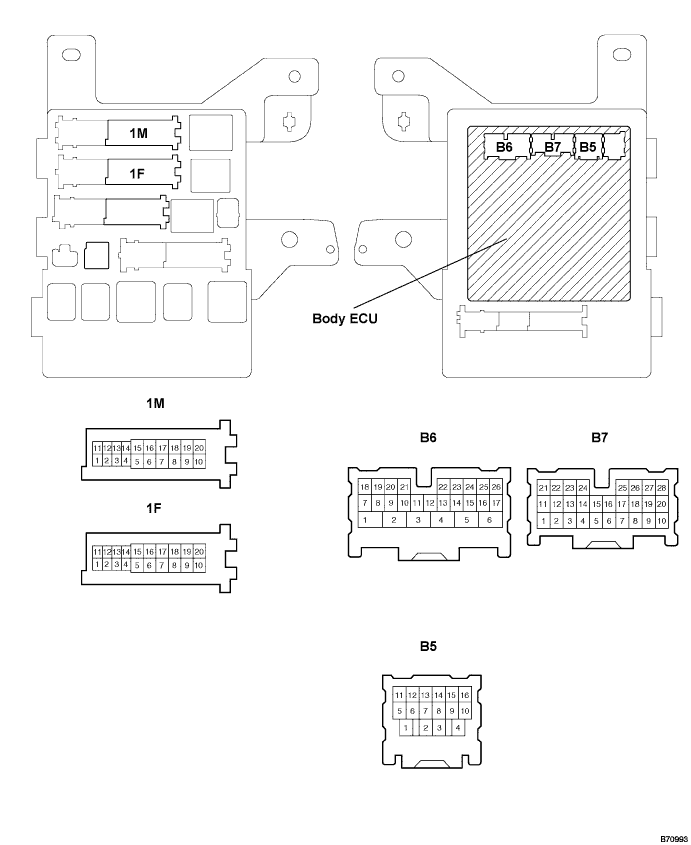
Disconnect the B5, B6 and B7 ECU connectors.
Disconnect the 1F and 1M J/B connectors.
Measure the resistance according to the value(s) in the table below.
| Symbols (Terminal No.) | Wiring Color | Terminal Description | Condition | Specified Condition |
| KSW (B6-21) - Body ground | B - Body ground | Key unlock warning switch input | No key in ignition key cylinder → Key inserted | 10 KΩ or higher → Below 1 Ω |
| PCTY (B7-23) - Body ground | L - W-B | Front passenger side courtesy switch input | Passenger side door CLOSED → OPEN | 10 KΩ or higher → Below 1 Ω |
| DCTY (B5-14) - Body ground | L - Body ground | Driver side courtesy switch input | Driver side door CLOSED → OPEN | 10 KΩ or higher → Below 1 Ω |
| GND1 (1F-10) - Body ground | W-B - Body ground | Ground | Constant | Below 1 Ω |
| GND2 (1M-9) - Body ground | W-B - Body ground | Ground | Constant | Below 1 Ω |
Reconnect the B4, B5 and B6 ECU connectors.
Reconnect the 1M and 1F J/B connectors.
Measure the voltage according to the value(s) in the table below.
| Symbols (Terminal No.) | Wiring Color | Terminal Description | Condition | Specified Condition |
| KSW (B6-21) - Body ground | B - Body ground | Key unlock warning switch input | No key in ignition key cylinder → Key inserted | 10 to 14 V → 0 V |
