POWER BACK DOOR SYSTEM > ECU Power Source Circuit

for Preparation Click here


DESCRIPTION

This circuit supplies power to operate the power back door ECU.

NOTICE:
The power back door ECU records the back door positions in the memory. In the case where any of the batteries, fuses, power back door ECU and power back door drive unit are removed and then reinstalled, the power back door ECU loses the memory of the door positions. In such a case, resetting the power back door system is necessary. Refer to the resetting operation specified in page Click here.


WIRING DIAGRAM


B111718E02


INSPECTION PROCEDURE

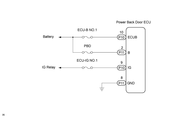
1.CHECK WIRE HARNESS (POWER BACK DOOR ECU - BATTERY AND BODY GROUND)


    B111734E02
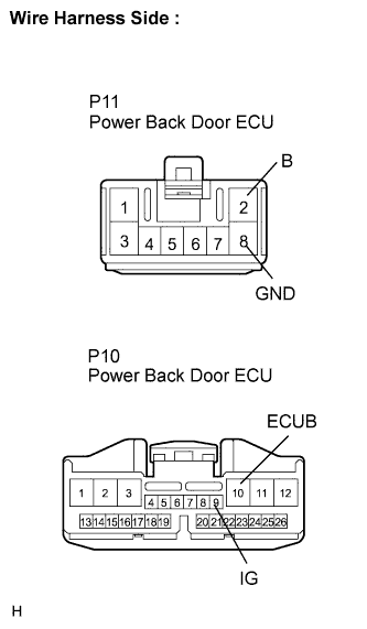
  1. Disconnect the power back door ECU connector.

  1. Measure the resistance according to the value(s) in the table below.

    Standard resistance:
    Tester Connection
    Condition
    Specified Condition
    P11-8 (GND) - Body ground
    Always
    Below 1 Ω

  1. Measure the voltage according to the value(s) in the table below.

    Standard voltage:
    Tester Connection
    Condition
    Specified Condition
    P10-10 (ECUB) - Body ground
    Always
    10 to 14 V
    P11-2 (B) - Body ground
    Always
    10 to 14 V
    P10-9 (IG) - Body ground
    Ignition switch ON
    10 to 14 V


NG
REPAIR OR REPLACE HARNESS OR CONNECTOR
OK

PROCEED TO NEXT CIRCUIT INSPECTION SHOWN IN PROBLEM SYMPTOMS TABLE