LIGHTING SYSTEM > AFS OFF Switch Circuit |
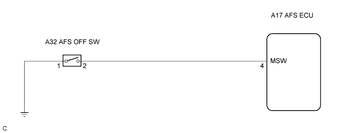
| 1.INSPECT AFS OFF SWITCH |
Disconnect the AFS OFF switch connector.
Measure the resistance according to the value(s) in the table below.
| Tester connection | Condition | Specified resistance |
| 1 - 2 | AFS OFF switch is pushed | Below 1 Ω |
| 1 - 2 | AFS OFF switch is not pushed | 10 kΩ or higher |
|
| ||||
| OK | |
| 2.INSPECT AFS ECU |
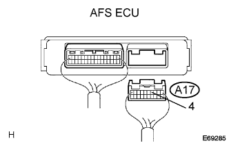 |
Disconnect the AFS ECU connector.
Measure the resistance according to the value(s) in the table below.
| Tester connection | Condition | Specified condition |
| A17-4 - Body ground | AFS OFF switch is pushed | Below 1 Ω |
| A17-4 - Body ground | AFS OFF switch is not pushed | 10 kΩ or higher |
|
| ||||
| OK | ||
| ||
