PARKING ASSIST MONITOR SYSTEM > TERMINALS OF ECU |
| TELEVISION CAMERA ASSEMBLY |
Disconnect the T14 camera connector.

Measure the voltage and resistance of each terminal of the wire harness side connector.
| Symbols (Terminal No.) | Wiring Color | Terminal Description | Condition | Specified value |
| CGND (T14-3) - Body ground | W - Body ground | Power ground | Always | Below 1 Ω |
| CB+ (T14-4) - CGND (T14-3) | B - W | Power source | IG switch ON, shift lever R position | Approx. 6 V |
Reconnect the T14 camera connector.
Measure the voltage and frequency of each terminal of the connector.
| Symbols (Terminal No.) | Wiring Color | Terminal Description | Condition | Specified value |
| CV+ (T14-2) - CV- (T14-1) | R - Shielded | Display signal | IG switch ON, shift lever R position | See waveform 1 |
 |
Reference:
Oscilloscope waveform
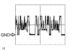
Waveform 1
| Item | Content |
| Measure terminal | CV+ - CV- |
| Measure set | 0.2 V/DIV, 0.2 μS/DIV |
| Condition | Ignition switch: ON, Shift lever: R position |
| TELEVISION CAMERA ECU |
Disconnect the T15, T16 and T17 ECU connector.
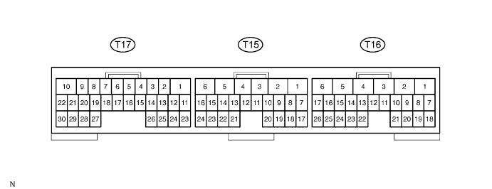
Measure the voltage and resistance of each terminal of the wire harness side connector.
| Symbols (Terminal No.) | Wiring Color | Terminal Description | Condition | Specified value |
| TX+ (T15-17) - Body ground | GR - Body ground | AVC-LAN control bus | Always | 10 kΩ or higher |
| TX- (T15-18) - Body ground | B - Body ground | AVC-LAN control bus | Always | 10 kΩ or higher |
| TX1- (T15-23) - Body ground | Y - Body ground | AVC-LAN control bus | Always | 10 kΩ or higher |
| TX1+ (T15-24) - Body ground | R - Body ground | AVC-LAN control bus | Always | 10 kΩ or higher |
| +B (T16-1) - GND1 (T16-6) | L - W-B | Battery Supply | Always | 10 to 14 V |
| IG (T16-2) - GND1 (T16-6) | B - W-B (*1) GR - W-B (*2) | IG signal input | IG switch ON | 10 to 14 V |
| ACC (T16-3) - GND1 (T16-6) | P - W-B | ACC signal input | IG switch ON or ACC | 10 to 14 V |
| GND1 (T16-6) - Body ground | W-B - Body ground | Power ground | Always | Below 1 Ω |
| CANL (T17-17) - Body ground | Y - Body ground | CAN control bus | Always | 10 kΩ or higher |
| CANH (T17-18) - Body ground | R - Body ground | CAN control bus | Always | 10 kΩ or higher |
Reconnect the T15, T16 and T17 ECU connector.
Measure the voltage and frequency of each terminal of the connector.
| Symbols (Terminal No.) | Wiring Color | Terminal Description | Condition | Specified value |
| VG (T15-7) - GND1 (T16-6) | Shielded - W-B | Display signal output ground (Shielded) | Always | Below 1 Ω |
| R (T15-8) - GND1 (T16-6) | G - W-B | Display signal output (Red) | While displaying map or back monitor | See waveform 2 |
| G (T15-9) - GND1 (T16-6) | W - W-B | Display signal output (Green) | While displaying map or back monitor | See waveform 2 |
| B (T15-10) - GND1 (T16-6) | R - W-B | Display signal output (Blue) | While displaying map or back monitor | See waveform 2 |
| B1 (T15-13) - GND1 (T16-6) | R - W-B | Display signal input (Blue) | While displaying map | See waveform 2 |
| G1 (T15-14) - GND1 (T16-6) | W - W-B | Display signal input (Green) | While displaying map | See waveform 2 |
| R1 (T15-15) - GND1 (T16-6) | G - W-B | Display signal input (Red) | While displaying map | See waveform 2 |
| VG1 (T15-16) - GND1 (T16-6) | Shielded - W-B | Display signal input ground (Shielded) | Always | Below 1 Ω |
| SYNC (T15-19) - GND1 (T16-6) | B - W-B | Synchronized signal output | While displaying map or back monitor | See waveform 3 |
| VR (T15-20) - GND1 (T16-6) | Y - W-B | Display signal output ground | Always | Below 1 Ω |
| VR1 (T15-21) - GND1 (T16-6) | Y - W-B | Display signal input ground | Always | Below 1 Ω |
| SYN1 (T15-22) - GND1 (T16-6) | B - W-B | Synchronized signal input | While displaying map | See waveform 3 |
| CGND (T17-21) - GND1 (T16-6) | W - W-B | Television camera ground | Always | Below 1 Ω |
| CB+ (T17-22) - GND1 (T16-6) | B - W-B | Power source to television camera | IG switch ON, shift lever R position | Approx. 6 V |
| CV- (T17-29) - GND1 (T16-6) | Shielded - W-B | Television camera ground (Shielded) | Always | Below 1 Ω |
| CV+ (T17-30) - GND1 (T16-6) | R - W-B | Display signal of television camera input | IG switch ON, shift lever R position | See waveform 1 |
|
Reference:
Oscilloscope waveform
Waveform 1
| Item | Content |
| Measure terminal | CV+ - GND1 |
| Measure set | 0.2 V/DIV, 0.2 μS/DIV |
| Condition | Ignition switch: ON, Shift lever: R position |
 |
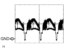
Waveform 2
| Item | Content |
| Terminal | R, G, B, R1, G1, B1, - GND1 |
| Measure set | 200 mV/DIV, 10 μS/DIV |
| Condition | Image is being displayed (Parking assist system or navigation system). |
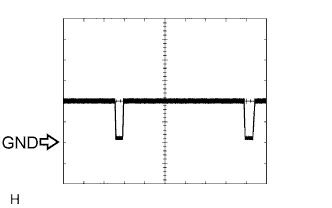 |
Waveform 3
| Item | Content |
| Terminal | SYNC, SYN1 - GND1 |
| Measure set | 500 mV/DIV, 10 μS/DIV |
| Condition | Image is being displayed (Parking assist system or navigation system). |
