PARKING ASSIST MONITOR SYSTEM > Television Camera ECU Power Source Circuit |
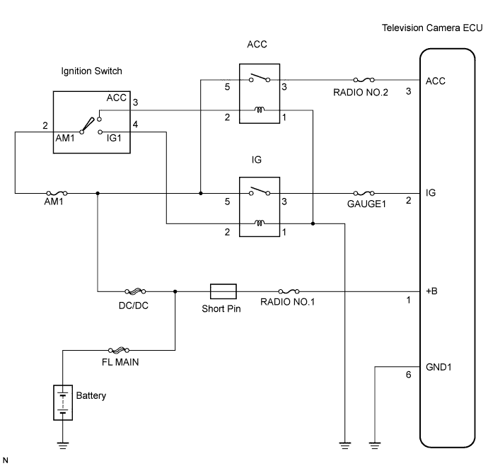
| 1.CHECK WIRE HARNESS AND CONNECTOR (BATTERY, BODY GROUND AND TELEVISION CAMERA ECU) |
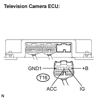 |
Disconnect the T16 connector from the television camera ECU.
Measure the resistance according to the value(s) in the table below.
| Tester connection (Terminal No.) | Condition | Specified condition |
| GND1 (T16-6) - Body ground | Always | Below 1 Ω |
Measure the voltage according to the value(s) in the table below.
| Tester connection (Terminal No.) | Condition | Specified condition |
| +B (T16-1) - GND1 (T16-6) | Always | 10 to 16 V |
| IG (T16-2) - GND1 (T16-6) | IG SW ON | 10 to 16 V |
| ACC (T16-3) - GND1 (T16-6) | IG SW ACC | 10 to 16 V |
|
| ||||
| OK | ||
| ||
