KEY REMINDER WARNING SYSTEM > Unlock Warning Switch Circuit

for Preparation Click here


DESCRIPTION

The unlock warning switch detects if the key is in the ignition key cylinder.
The unlock warning switch turns on when the key is inserted into the ignition key cylinder and turns off when the key is removed from the cylinder.
The body ECU is connected to the unlock warning switch via terminal KSW and key detection status signals are input to the ECU.
The body ECU applies voltage to the unlock warning switch via terminal KSW. When the unlock warning switch is on (there is continuity between the switch terminals), a signal indicating that the key is in the ignition key cylinder is input to the body ECU. When the switch is off (there is no continuity between the switch terminals), a signal indicating that the key is not in the cylinder is input.

WIRING DIAGRAM


B109773E24


INSPECTION PROCEDURE

1.READ VALUE OF DATA LIST (UNLOCK WARNING SWITCH)
  1. Check the DATA LIST to ensure proper operation of the door unlock detection switch.

    Body ECU: 
    Item
    Measurement Item /
    Display (Range)
    Normal Condition
    Diagnostic Note
    Key Unlock Warning SW
    Unlock warning switch signal
    /ON or OFF
    ON: Key is in ignition key cylinder
    OFF: No key is in ignition key cylinder
    -

    OK:
    The display is as specified in the normal condition.


NG
Go to step 2
OK

PROCEED TO NEXT CIRCUIT INSPECTION SHOWN IN PROBLEM SYMPTOMS TABLE 

2.INSPECT UNLOCK WARNING SWITCH ASSEMBLY


    B067252E02
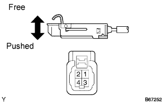
  1. Remove the unlock warning switch assembly.

  1. Measure the resistance according to the value(s) in the table below.

    Standard resistance:
    Tester Connection
    Condition
    Specified Condition
    1 - 2
    Free
    10 kΩ or higher
    1 - 2
    Pushed
    Below 1 Ω


NG
REPLACE UNLOCK WARNING SWITCH ASSEMBLY
OK


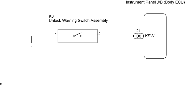
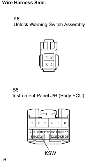
3.CHECK WIRE HARNESS (UNLOCK WARNING SWITCH - INSTRUMENT PANEL J/B (BODY ECU))


    B111724E02
  1. Disconnect the unlock warning switch assembly connector.

  1. Disconnect the instrument panel J/B connector.

  1. Measure the resistance according to the value(s) in the table below.

    Standard resistance:
    Tester Connection
    Condition
    Specified Condition
    K6-2 - B6-21 (KSW)
    Always
    Below 1 Ω
    K6-1 - Body ground
    Always
    Below 1 Ω


NG
REPAIR OR REPLACE HARNESS OR CONNECTOR
OK

PROCEED TO NEXT CIRCUIT INSPECTION SHOWN IN PROBLEM SYMPTOMS TABLE