INSTRUMENT PANEL SAFETY PAD > INSTALLATION |
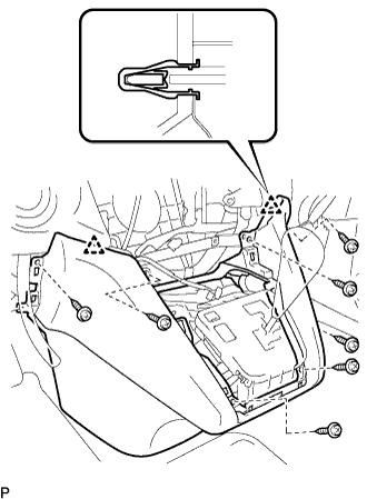
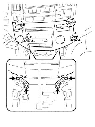
| 1. INSTALL INSTRUMENT PANEL ASSEMBLY |
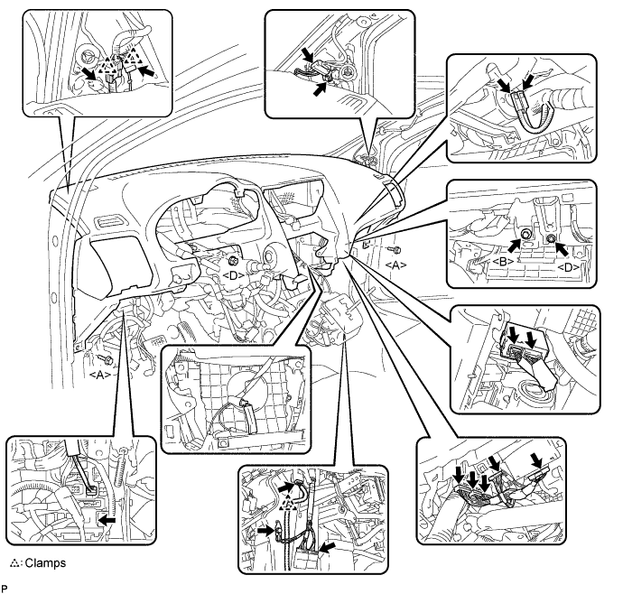
Connect each of the clamps and connectors.
Install the 2 bolts <A>, bolt <B>, and 2 nuts <D> as shown illustration below to install the instrument panel assembly.
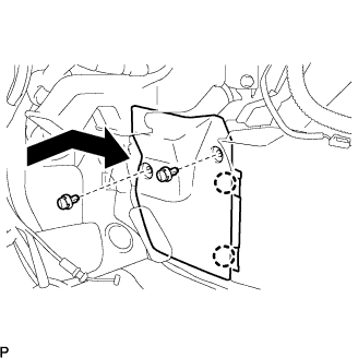
| 2. INSTALL INSTRUMENT PANEL NO.1 REGISTER ASSEMBLY LOWER |
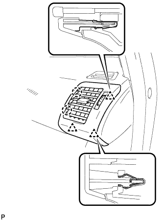 |
Engage the 3 clips and 2 claws, and install the instrument panel No.1 register assembly lower.
| 3. INSTALL INSTRUMENT PANEL NO.1 REGISTER ASSEMBLY |
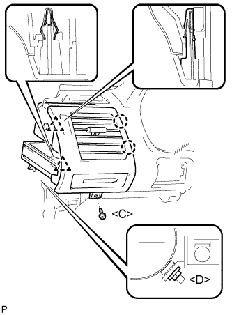 |
Engage the 2 clips and the 2 claws.
Install the screw <C>, nut <D>, and the instrument panel No.1 register assembly.
| 4. INSTALL INSTRUMENT PANEL FINISH PLATE |
| 5. INSTALL FRONT PILLAR GARNISH LH |
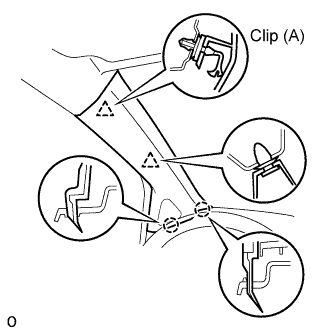 |
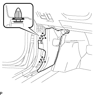
Install a new clip (A) on the front pillar garnish.
Engage the 2 claws and 2 clips, and install the front pillar garnish.
| 6. INSTALL FRONT PILLAR GARNISH RH |
| 7. INSTALL INSTRUMENT PANEL FINISH PANEL LOWER CENTER |
 |
Engage the 2 clips.
Install the 7 screws <C> and the instrument panel finish panel lower center.
| 8. INSTALL FLOOR CARPET COVER CENTER LH |
 |
Slide the floor carpet cover center LH to the rear of the vehicle, and engage the 2 claws to the instrument panel finish panel lower center at the floor carpet cover center LH.
Install the 2 clips and the floor carpet cover center LH.
| 9. INSTALL FLOOR CARPET COVER CENTER RH |
| 10. INSTALL GLOVE COMPARTMENT DOOR ASSEMBLY |
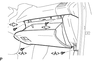 |
Connect the connectors.
Install the 2 bolts <A>, the 2 screws <C>, and the glove compartment door assembly.
| 11. INSTALL INSTRUMENT PANEL NO.2 UNDER COVER SUB-ASSEMBLY |
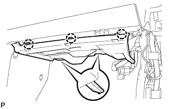 |
Connect the connectors.
Engage the 3 claws and install the instrument panel No.2 under cover sub-assembly.
| 12. INSTALL COWL SIDE TRIM SUB-ASSEMBLY RH |
| 13. INSTALL FRONT DOOR SCUFF PLATE RH |
| 14. INSTALL COMBINATION METER ASSEMBLY |
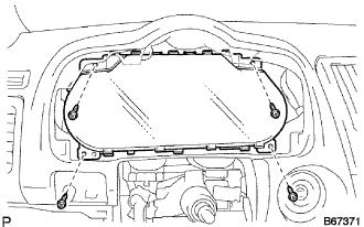 |
Connect the connectors.
Install the 4 screws <C> and the combination meter assembly.
| 15. INSTALL INSTRUMENT CLUSTER FINISH PANEL SUB-ASSEMBLY |
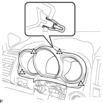 |
Engage the 4 clips and install the instrument cluster finish panel sub-assembly.
| 16. INSTALL DRIVER SIDE KNEE AIRBAG ASSEMBLY |
Install the driver side knee airbag assembly with the 4 bolts.
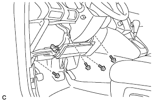 |
Connect the connector to the driver side knee airbag assembly.
| 17. INSTALL INSTRUMENT PANEL FINISH PANEL SUB-ASSEMBLY LOWER |
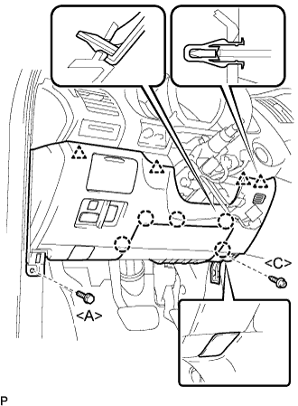 |
Connect the connectors.
Engage the 5 claws and the 4 clips.
Connect the hood lock control cable assembly.
Install the bolt <A>, the screw <C>, and the instrument panel finish panel sub-assembly lower.
| 18. INSTALL COWL SIDE TRIM SUB-ASSEMBLY LH |
 |
Install the 2 clips and the cowl side trim sub-assembly LH.
| 19. INSTALL FRONT DOOR SCUFF PLATE LH |
 |
Connect the connector. (w/ illumination scuff plate)
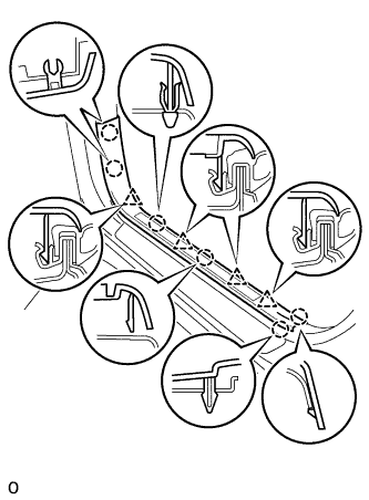
Engage the 6 claws and 4 clips, and install the front door scuff plate.
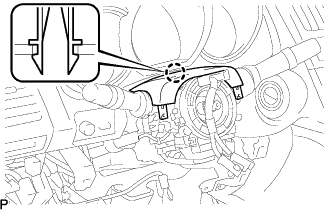
| 20. INSTALL TURN SIGNAL SWITCH ASSEMBLY WITH SPIRAL CABLE SUB-ASSEMBLY |
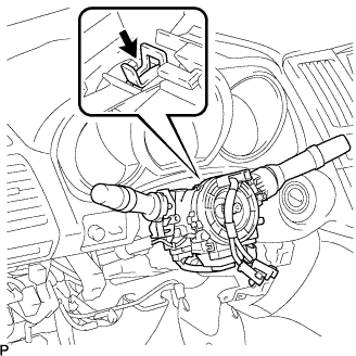 |
Install the turn signal switch assembly with spiral cable sub-assembly to the steering column assembly with the clamp.
Connect the connectors to the turn signal switch assembly with spiral cable sub-assembly.
| 21. INSTALL TILT AND TELESCOPIC SWITCH (w/ Power Tilt and Power Telescopic) |
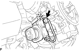 |
Engage the claw to install the tilt and telescopic switch.
Connect the connector.
| 22. INSTALL STEERING COLUMN COVER |
 |
Engage the claw to install the steering column cover upper.
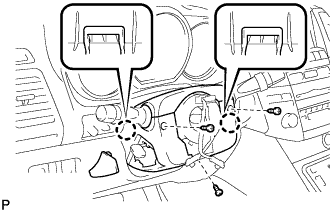 |
Engage the 2 claws to install the steering column cover lower.
Install the 3 screws.
Install the steering column cover No.2.
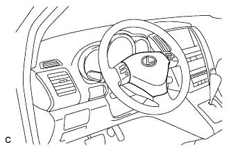
| 23. INSTALL STEERING WHEEL ASSEMBLY |
Align the matchmarks on the steering wheel assembly and steering main shaft assembly.
Install the steering wheel assembly set nut.
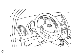
| 24. INSTALL STEERING PAD |
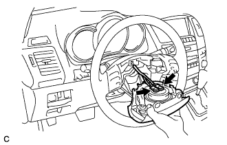 |
Support the steering pad with one hand as shown in the illustration.
Connect the 2 connectors to the steering pad.
Connect the horn connector.
Confirm that the circumference groove of the "torx" screw fits in the screw case, and place the steering pad onto the steering wheel assembly.
Using a "torx" socket wrench (T30), tighten the 2 "torx" screws.
| 25. INSTALL STEERING WHEEL NO.3 COVER LOWER |
 |
Install the steering wheel No.3 cover lower.
| 26. INSTALL STEERING WHEEL NO.2 COVER LOWER |
 |
Install the steering wheel No.2 cover lower.
| 27. INSTALL MULTI-DISPLAY (w/ Navigation System) |
 |
Connect the connectors.
Engage the 4 clips and install the multi-display with the 2 bolts.
| 28. INSTALL CENTER CLUSTER INTEGRATION SWITCH (w/o Navigation System) |
 |
Install the connector.
Install the center cluster integration switch with the 2 bolts.
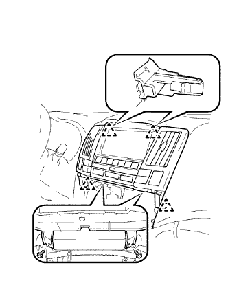
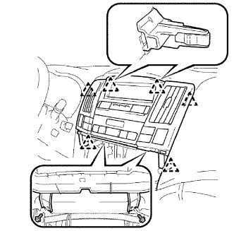
| 29. INSTALL RADIO RECEIVER |
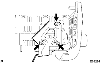 |
Install the No.2 radio bracket with the 3 bolts.
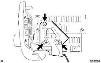 |
Install the No.1 radio bracket with the 3 bolts.
 |
Connect the connectors.
Engage the 2 claws and the 2 clips.
Install the radio receiver with bracket with the 4 bolts.
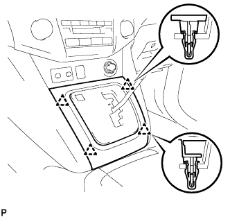
| 30. INSTALL INSTRUMENT PANEL FINISH PANEL LOWER |
 |
Connect the connectors.
Engage the 2 clips and install the instrument panel finish panel lower.
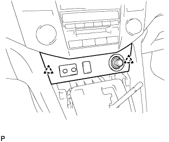
| 31. INSTALL CONSOLE PANEL UPPER FRONT |
 |
Engage the 4 clips and install the console panel upper front.
| 32. INSTALL SHIFT LEVER KNOB SUB-ASSEMBLY |
| 33. CONNECT CABLE TO NEGATIVE BATTERY TERMINAL |
| 34. PERFORM INITIALIZATION |
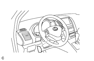
| 35. INSPECT STEERING PAD |
Perform a diagnostic system check (Click here).
 |
With the steering pad installed on the vehicle, perform a visual check. If there are any defects as mentioned below, replace the steering pad with a new one:
| 36. INSPECT SRS WARNING LIGHT |
