INSTRUMENT PANEL SAFETY PAD > DISASSEMBLY |
| 1. REMOVE SPEAKER HOLE NO.1 COVER (w/ Mark Levinson Speaker System) |
 |
Disengage the 4 clips and remove the speaker hole No.1 cover.
| 2. REMOVE INSTRUMENT PANEL NO.1 SPEAKER PANEL SUB-ASSEMBLY |
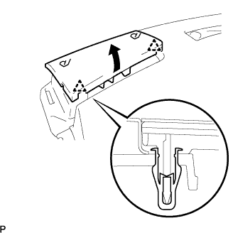 |
Disengage the 2 clips and remove the instrument panel No.1 speaker panel sub-assembly.
| 3. REMOVE INSTRUMENT PANEL NO.2 SPEAKER PANEL SUB-ASSEMBLY |
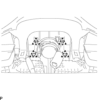
| 4. REMOVE FRONT NO.2 SPEAKER (w/ Mark Levinson Speaker System) |
 |
Remove the 2 bolts.
Disconnect the connector and remove the front No.2 speaker.
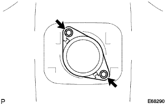
| 5. REMOVE FRONT NO.2 SPEAKER |
 |
Remove the 2 bolts and the front No.2 speaker.
Disconnect the connector.
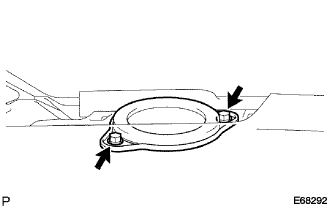
| 6. REMOVE FRONT NO.2 SPEAKER |
|
Remove the 2 bolts and the front No.2 speaker.
Disconnect the connector.
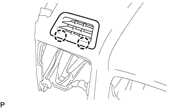
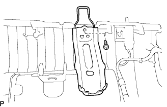
| 7. REMOVE LIGHT CONTROL RHEOSTAT |
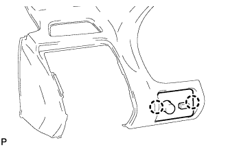 |
Disengage the 2 claws and remove the light control rheostat.
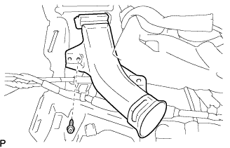
| 8. REMOVE SIDE DEFROSTER NO.3 NOZZLE DUCT |
 |
Remove the screw <C> and the side defroster No.3 nozzle duct.
| 9. REMOVE SIDE DEFROSTER NO.4 NOZZLE DUCT |
| 10. REMOVE INSTRUMENT PANEL NO.1 PIN |
 |
Remove the screw <C> and the instrument panel No.1 pin.
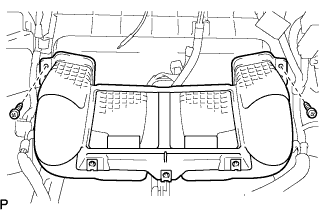
| 11. REMOVE DEFROSTER NOZZLE ASSEMBLY |
 |
Remove the 3 screws <C> and the defroster nozzle assembly.
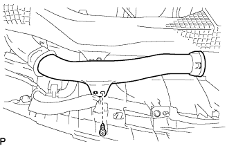
| 12. REMOVE HEATER TO REGISTER NO.1 DUCT |
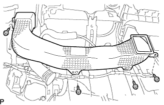 |
Remove the 4 screws <C> and the heater to register No.1 duct.
| 13. REMOVE HEATER TO REGISTER NO.4 DUCT |
| 14. REMOVE HEATER TO REGISTER CENTER SUB DUCT |
 |
Remove the 2 screws <C> and the heater to register center sub duct.
| 15. REMOVE SIDE DEFROSTER NO.1 NOZZLE DUCT |
 |
Remove the screw <C> and the side defroster No.1 nozzle duct.
| 16. REMOVE SIDE DEFROSTER NO.2 NOZZLE DUCT |
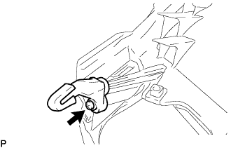
| 17. REMOVE SIDE DEFROSTER NO.1 NOZZLE |
 |
Disengage the 2 claws and remove the side defroster No.1 nozzle.
| 18. REMOVE SIDE DEFROSTER NO.2 NOZZLE |
| 19. REMOVE WINDSHIELD WIPER RELAY ASSEMBLY (w/ Rain Sensor) |
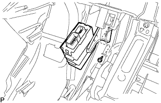 |
Remove the screw <C> and the windshield wiper relay assembly.
| 20. REMOVE NETWORK GATEWAY ECU |
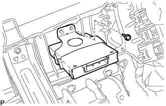 |
Remove the screw <C> and the network gateway ECU.
| 21. REMOVE DOOR OPENING RELAY ASSEMBLY |
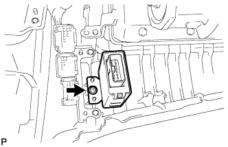 |
Remove the screw <C> and the door opening relay assembly.
| 22. REMOVE DEFROSTER NOZZLE NO.1 GARNISH |
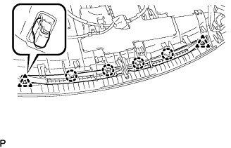 |
Disengage the 2 clips and 4 claws, then remove the defroster nozzle No.1 garnish.
| 23. REMOVE INSTRUMENT PANEL BRACKET SUB-ASSEMBLY CENTER |
 |
Remove the screw <C> and the instrument panel bracket sub-assembly center.
| 24. REMOVE GLOVE BOX LIGHT ASSEMBLY |
 |
Disconnect the connector.
Disengage the 2 claws and remove the glove box light assembly.
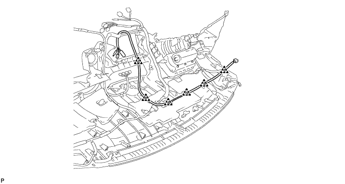
| 25. REMOVE NO.2 RADIO ANTENNA CORD (w/o Navigation System) |
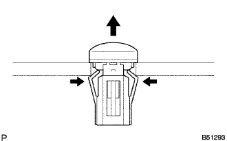
Disconnect the 6 clamps and remove the No.2 radio antenna cord.
| 26. REMOVE NO.2 RADIO ANTENNA CORD (w/ Navigation System) |
Remove the 2 screws and the navigation antenna.
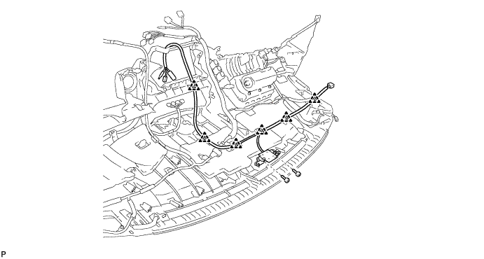
Disengage the 6 clamps and remove the No.2 radio antenna cord.
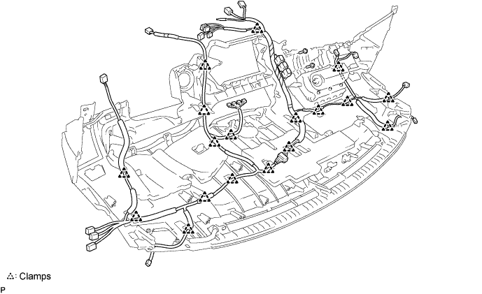
| 27. REMOVE INSTRUMENT PANEL NO.2 WIRE |
Remove the 2 screws.
Disengage the 18 clamps and remove the instrument panel No.2 wire.
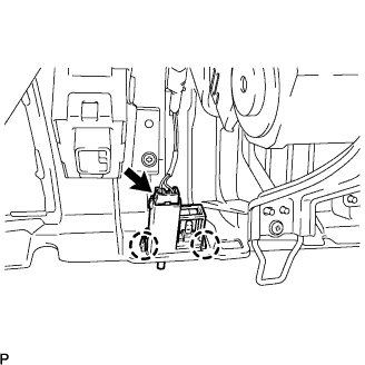
| 28. REMOVE AUTOMATIC LIGHT CONTROL SENSOR |
 |
Remove the automatic light control sensor.
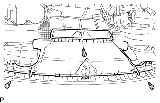
| 29. REMOVE FRONT PASSENGER AIRBAG ASSEMBLY |
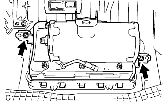 |
Remove the 2 screws.
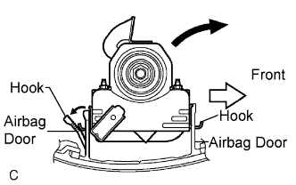 |
Release the rear side airbag door from the hook by slightly deflecting it and roll the front passenger airbag assembly forward.
Release the front side airbag door from the other hook and remove the front passenger airbag assembly.
