THEFT DETERRENT SYSTEM > ECU Power Source Circuit |
| 1.INSPECT FUSE (ECU-B NO.1) |
Remove the ECU-B NO.1 fuse from the fusible link block.
Measure the resistance.
|
| ||||
| OK | |
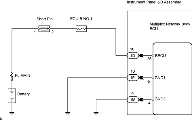
| 2.CHECK INSTRUMENT PANEL J/B ASSEMBLY (MULTIPLEX NETWORK BODY ECU) (POWER SOURCE) |
Install the ECU-B NO.1 fuse to the fusible link block.
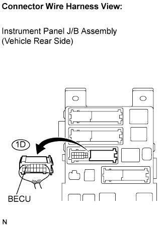 |
Disconnect the 1D J/B connector.
Measure the voltage according to the value(s) in the table below.
| Symbol (Tester Connection) | Specified Condition |
| BECU (1D-10) - Body ground | 10 to 14 V |
|
| ||||
| OK | |
| 3.CHECK HARNESS AND CONNECTOR (INSTRUMENT PANEL J/B - BODY GROUND) |
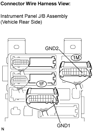 |
Disconnect the 1F and 1M J/B connectors.
Measure the resistance according to the value(s) in the table below.
| Symbol (Tester Connection) | Specified Condition |
| GND1 (1F-10) - Body ground | Below 1 Ω |
| GND2 (1M-9) - Body ground |
|
| ||||
| OK | ||
| ||
