THEFT DETERRENT SYSTEM > Ignition Switch Circuit |
| 1.READ DATA LIST BY INTELLIGENT TESTER |
Connect the intelligent tester to the DLC3.
Turn the ignition switch ON.
Turn the intelligent tester main switch on.
Select the item below in the DATA LIST and read the display on the tester.
| Item | Test Details | Diagnostic Note |
| IG SW | Ignition switch signal ON/OFF | - |
|
| ||||
| OK | ||
| ||
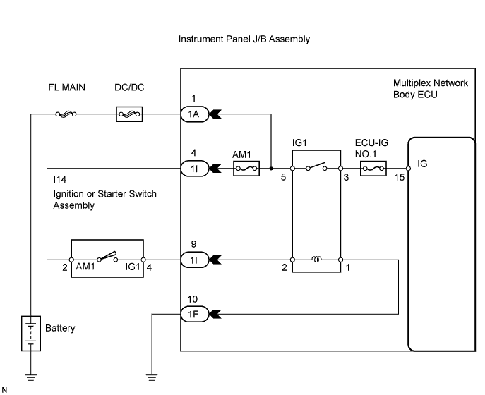
| 2.INSPECT FUSES (ECU-IG NO.1, AM1) |
Remove the ECU-IG NO.1 and AM1 fuses from the instrument panel J/B.
Measure the resistance.
|
| ||||
| OK | |
| 3.INSPECT RELAY (IG1) |
Install the ECU-IG NO.1 and AM1 fuses to the instrument panel J/B.
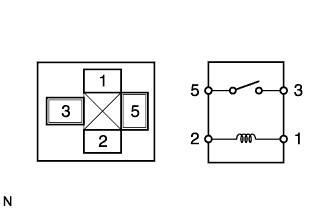 |
Remove the IG1 relay from the instrument panel J/B.
Measure the resistance according to the value(s) in the table below.
| Tester Condition | Specified Condition |
| 3 - 5 | 10 kΩ or higher |
| Below 1 Ω (When battery voltage is applied to terminals 1 and 2) |
|
| ||||
| OK | |
| 4.INSPECT IGNITION OR STARTER SWITCH ASSEMBLY |
Install the IG1 relay to the instrument panel J/B.
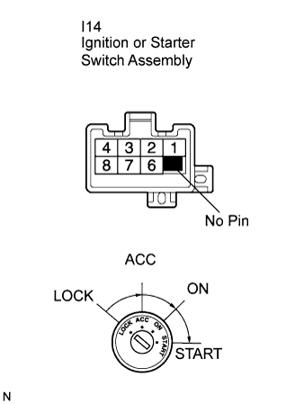 |
Disconnect the I14 switch connector.
Measure the resistance according to the value(s) in the table below.
| Tester Connection | Switch Position | Specified Condition |
| 2 - 4 | ON | Below 1 Ω |
|
| ||||
| OK | |
| 5.CHECK HARNESS AND CONNECTOR (BATTERY - INSTRUMENT PANEL J/B ASSEMBLY) |
Connect the I14 switch connector.
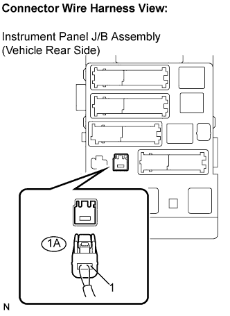 |
Disconnect the 1A J/B connector.
Measure the voltage according to the value(s) in the table below.
| Symbol (Tester Connection | Switch Position | Specified Condition |
| IG (1A-1) - Body ground | Ignition switch ON | 10 to 14 V |
|
| ||||
| OK | |
| 6.CHECK HARNESS AND CONNECTOR (INSTRUMENT PANEL J/B - INSTRUMENT PANEL J/B) |
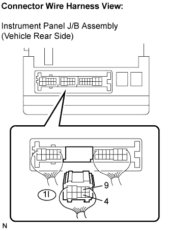 |
Disconnect the 1I J/B connector.
Measure the resistance according to the value(s) in the table below.
| Tester Connection | Switch Position | Specified Condition |
| 1I-4 - 1I-9 | Ignition switch ON | Below 1 Ω |
|
| ||||
| OK | |
| 7.CHECK HARNESS AND CONNECTOR (INSTRUMENT PANEL J/B (BODY ECU) - BODY GROUND) |
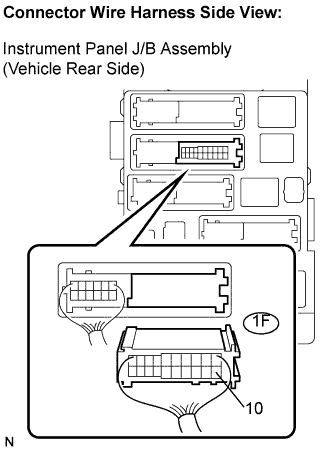 |
Disconnect the 1F J/B connector.
Measure the resistance according to the value(s) in the table below.
| Tester Connection | Specified Condition |
| 1F-10 - Body ground | Below 1 Ω |
|
| ||||
| OK | ||
| ||
