THEFT DETERRENT SYSTEM > Security Indicator Light Circuit |
| 1.PERFORM ACTIVE TEST BY INTELLIGENT TESTER |
Connect the intelligent tester to the DLC3.
Turn the ignition switch on ON.
Turn the intelligent tester main switch on.
Select the item below in the ACTIVE TEST and then check that the indicator operates.
| Item | Test Details | Diagnostic Note |
| Security Indicator | Security indicator ON/OFF | - |
|
| ||||
| OK | ||
| ||
| 2.INSPECT MULTI-DISPLAY ASSEMBLY OR CENTER CLUSTER INTEGRATION SWITCH ASSEMBLY (SECURITY INDICATOR) |
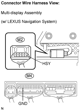 |
w/ LEXUS navigation system:
Check the security indicator.
Remove the multi-display.
Apply battery voltage to the terminals of the multi-display and check the lighting condition of the security indicator.
| Measurement Condition | Specified Condition |
| Battery positive (+) → Terminal 1 (HSY) (M2 side) Battery positive (-) → Terminal 3 (GND) (M4 side) | Lights up |
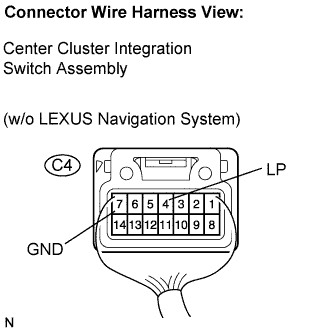 |
w/o LEXUS navigation system:
Check the security indicator.
Remove the center cluster integration switch.
Apply battery voltage to the terminals of the center cluster integration switch and check the lighting condition of the security indicator.
| Measurement Condition | Specified Condition |
| Battery positive (+) → Terminal 4 (LP) Battery positive (-) → Terminal 7 (GND) | Lights up |
|
| ||||
| OK | |
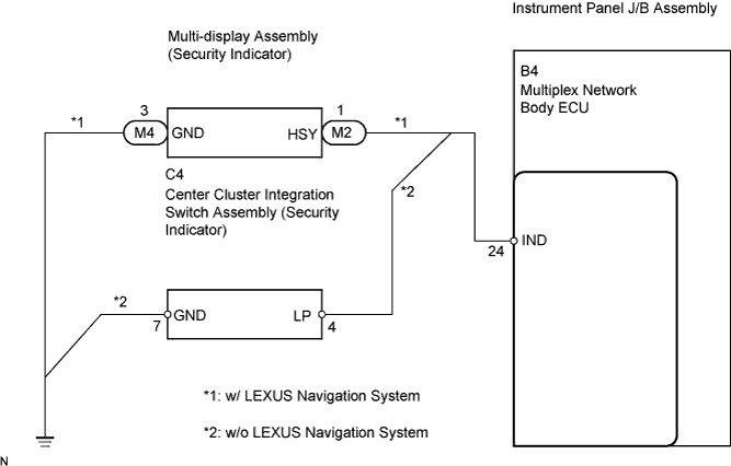
| 3.CHECK HARNESS AND CONNECTOR (BODY ECU - MULTI-DISPLAY OR CENTER CLUSTER INTEGRATION SW) |
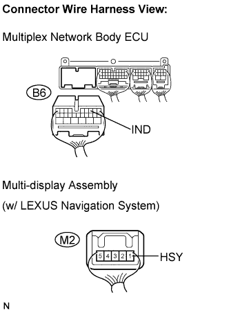 |
w/ LEXUS navigation system:
Check the wire harness between the ECU and multi-display.
Disconnect the B6 ECU connector and M2 multi-display connector.
Measure the resistance according to the value(s) in the table below.
| Symbol (Tester Connection) | Specified Condition |
| IND (B6-24) - HSY (M2-1) | Below 1 Ω |
| IND (B6-24) or HSY (M2-1) - Body ground | 10 kΩ or higher |
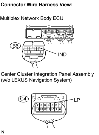 |
w/o LEXUS navigation system:
Check the wire harness between the ECU and integration switch.
Disconnect the B6 ECU connector and C4 switch connector.
Measure the resistance according to the value(s) in the table below.
| Symbol (Tester Connection) | Specified Condition |
| IND (B6-24) - LP (C4-4) | Below 1 Ω |
| IND (B6-24) or LP (C4-4) - Body ground | 10 kΩ or higher |
|
| ||||
| OK | |
| 4.CHECK HARNESS AND CONNECTOR (MULTI-DISPLAY OR CENTER CLUSTER INTEGRATION SW - BODY GROUND) |
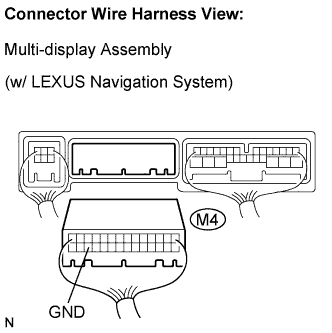 |
w/ LEXUS navigation system:
Check the wire harness between the multi-display and the body ground.
Disconnect the M4 multi-display connector.
Measure the resistance according to the value(s) in the table below.
| Symbol (Tester Connection) | Specified Condition |
| GND (M4-3) - Body ground | Below 1 Ω |
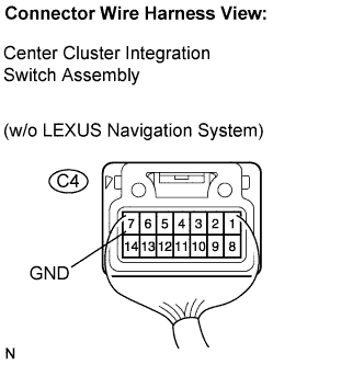 |
w/o LEXUS navigation system:
Check the wire harness between the integration switch and the body ground.
Disconnect the C4 switch connector.
Measure the resistance according to the value(s) in the table below.
| Symbol (Tester Connection) | Specified Condition |
| GND (C4-7) - Body ground | Below 1 Ω |
|
| ||||
| OK | ||
| ||
