THEFT DETERRENT SYSTEM > DIAGNOSIS SYSTEM |
| DESCRIPTION |
The multiplex network body ECU controls the functions of the theft deterrent system on the vehicle. Theft deterrent system data can be read in the Data Link Connector 3 (DLC3) of the vehicle. When the system seems to be malfunctioning, use the intelligent tester to check for a malfunction and perform repairs.
| DLC3 CHECK |
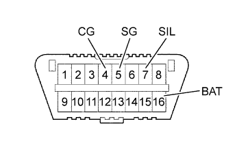 |
The vehicle's ECM uses the ISO 9141-2 (Euro-OBD)/ ISO 14230(M-OBD) communication protocol. The terminal arrangement of the DLC3 complies with ISO 15031-3 and matches the ISO 9141-2/ ISO 14230 format.
| Symbol | Terminal No. | Name | Reference terminal | Result | Condition |
| SIL | 7 | Bus "+" line | 5-Signal ground | Pulse generation | During transmission |
| CG | 4 | Chassis ground | Body ground | 1 Ω or less | Always |
| SG | 5 | Signal ground | Body ground | 1 Ω or less | Always |
| BAT | 16 | Battery positive | Body ground | 9 to 14 V | Always |
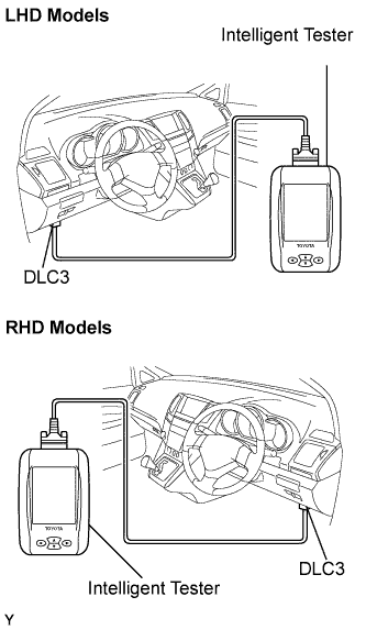 |
Connect the cable of the intelligent tester to the DLC3, turn the ignition switch ON and attempt to use the intelligent tester. If the screen displays a communication error message, a problem exists in the vehicle side or with the tester side.
| CHECK BATTERY VOLTAGE |
