REAR DOOR LOCK > INSPECTION |
| 1. INSPECT REAR DOOR LOCK ASSEMBLY LH (W/O DOUBLE LOCK SYSTEM) |
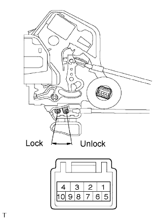 |
Apply battery voltage to the door lock and check operation of the motor.
| Measurement Condition | Specified Condition |
| Battery positive (+) → Terminal 4 Battery negative (-) → Terminal 1 | Lock |
| Battery positive (+) → Terminal 1 Battery negative (-) → Terminal 4 | Unlock |
Measure the resistance according to the value(s) in the table below.
| Tester Connection | Door Lock Position | Specified Condition |
| 6 - 9 | Lock | 10 kΩ or higher |
| 6 - 9 | Unlock | Below 1 Ω |
| 2. INSPECT REAR DOOR LOCK ASSEMBLY RH (W/O DOUBLE LOCK SYSTEM) |
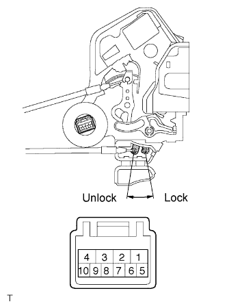 |
Apply battery voltage to the door lock and check operation of the motor.
| Measurement Condition | Specified Condition |
| Battery positive (+) → Terminal 4 Battery negative (-) → Terminal 1 | Lock |
| Battery positive (+) → Terminal 1 Battery negative (-) → Terminal 4 | Unlock |
Measure the resistance according to the value(s) in the table below.
| Tester Connection | Door Lock Position | Specified Condition |
| 6 - 9 | Lock | 10 kΩ or higher |
| 6 - 9 | Unlock | Below 1 Ω |
| 3. INSPECT REAR DOOR LOCK ASSEMBLY LH (W/ DOUBLE LOCK SYSTEM) |
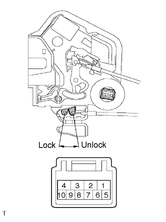 |
Apply battery voltage to the door lock and check operation of the motor.
| Measurement Condition | Specified Condition |
| Battery positive (+) → Terminal 2 Battery negative (-) → Terminal 1 | Lock |
| Battery positive (+) → Terminal 1 Battery negative (-) → Terminal 2 | Unlock |
Measure the resistance according to the value(s) in the table below.
| Tester Connection | Door Lock Position | Specified Condition |
| 5 - 6, 5 - 10 | Lock | 10 kΩ or higher |
| 5 - 6, 5 - 10 | Unlock | Below 1 Ω |
Check operation of the double lock motor.
Apply battery voltage and set the door lock motor to the lock position.
Apply battery voltage to the door lock and check operation of the double lock motor.
| Measurement Condition | Specified Condition |
| Battery positive (+) → Terminal 4 Battery negative (-) → Terminal 3 | Double Locking System is set |
| Battery positive (+) → Terminal 3 Battery negative (-) → Terminal 4 | Double Locking System is unset |
Check that the doors cannot be unlocked by operating the control cable while the double locking system is set.
Measure the resistance according to the value(s) in the table below.
| Tester Connection | Door Lock Position | Specified Condition |
| 6 - 9, 9 - 10 | Set | Below 1 Ω |
| 6 - 9, 9 - 10 | Unset | 10 kΩ or higher |
| 4. INSPECT REAR DOOR LOCK ASSEMBLY RH (W/ DOUBLE LOCK SYSTEM) |
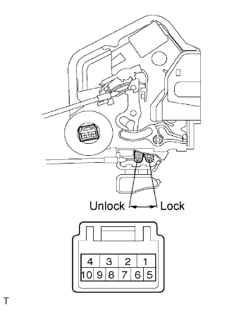 |
Apply battery voltage to the door lock and check operation of the motor.
| Measurement Condition | Specified Condition |
| Battery positive (+) → Terminal 4 Battery negative (-) → Terminal 3 | Lock |
| Battery positive (+) → Terminal 3 Battery negative (-) → Terminal 4 | Unlock |
Measure the resistance according to the value(s) in the table below.
| Tester Connection | Door Lock Position | Specified Condition |
| 6 - 9, 9 - 10 | Lock | 10 kΩ or higher |
| 6 - 9, 9 - 10 | Unlock | Below 1 Ω |
Check operation of the double lock motor.
Apply battery voltage and set the door lock motor to the lock position.
Apply battery voltage to the door lock and check operation of the double lock motor.
| Measurement Condition | Specified Condition |
| Battery positive (+) → Terminal 2 Battery negative (-) → Terminal 1 | Double Locking System is set |
| Battery positive (+) → Terminal 1 Battery negative (-) → Terminal 2 | Double Locking System is unset |
Check that the doors cannot be unlocked by operating the control cable while the double locking system is set.
Measure the resistance according to the value(s) in the table below.
| Tester Connection | Door Lock Position | Specified Condition |
| 5 - 6, 5 - 10 | Set | Below 1 Ω |
| 5 - 6, 5 - 10 | Unset | 10 kΩ or higher |
