AUDIO AND VISUAL SYSTEM > Vehicle Speed Signal Circuit between Stereo Component Amplifier and Combination Meter |
| 1.CHECK OPERATION OF SPEEDOMETER |
Drive the vehicle and check if the function of the speedometer on the combination meter is normal.
|
| ||||
| OK | |
| 2.INSPECT STEREO COMPONENT AMPLIFIER |
 |
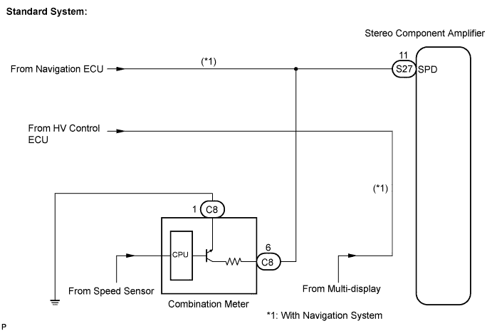
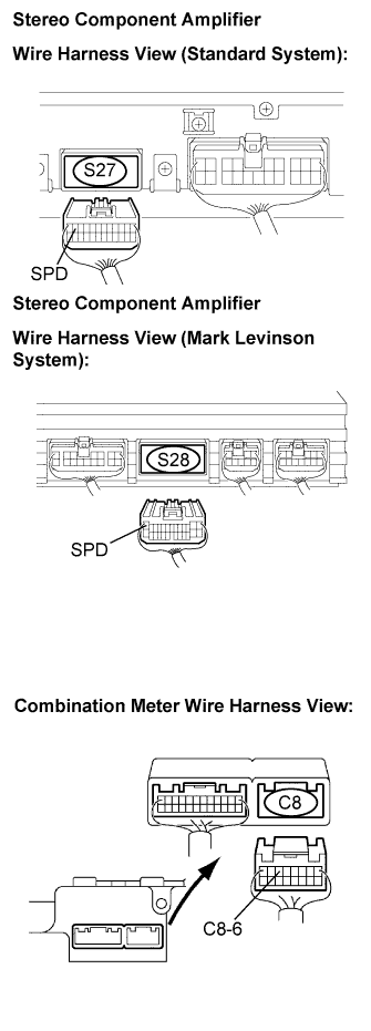
Standard System:
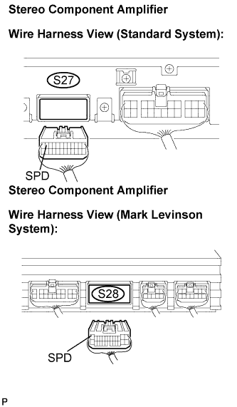
Disconnect the stereo component amplifier connector S27.
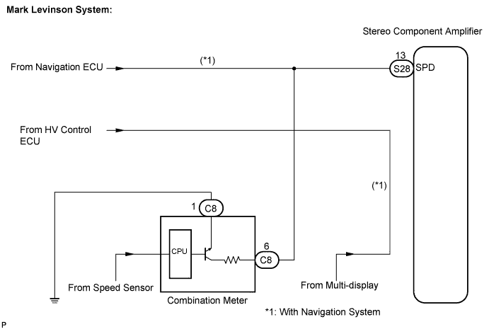
Mark Levinson System:
Disconnect the stereo component amplifier connector S28.
Measure voltage.
Jack up either one of the drive wheels.
Move the shift lever to the neutral position.
Turn the ignition switch to the ON position.
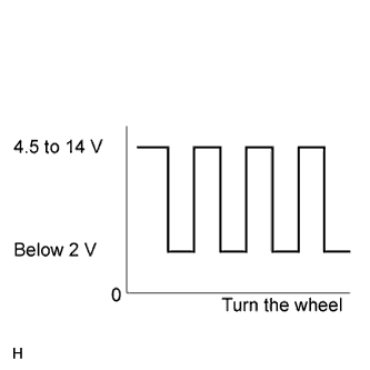 |
Measure the voltage between terminal SPD of the stereo component amplifier and body ground when the drive wheels are turned slowly.
|
| ||||
| OK | |
| 3.CHECK SYSTEM TYPE |
Choose type to be inspected.
| Type | Proceed to |
| Standard System | A |
| Mark Levinson System | B |
|
| ||||
| A | ||
| ||
| 4.CHECK HARNESS AND CONNECTOR (COMBINATION METER - STEREO COMPONENT AMPLIFIER) |
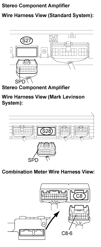 |
Standard System:
Disconnect the stereo component amplifier connector S27 and combination meter connector C8.
Mark Levinson System:
Disconnect the stereo component amplifier connector S28 and combination meter connector C8.
Measure the resistance according to the value(s) in the table below.
| Tester connection | Condition | Specified condition |
| SPD - C8-6 | Ignition switch OFF | Below 1 Ω |
|
| ||||
| OK | |
| 5.CHECK HARNESS AND CONNECTOR (COMBINATION METER - STEREO COMPONENT AMPLIFIER) |
 |
Standard System:
Disconnect the stereo component amplifier connector S27 and combination meter connector C8.
Mark Levinson System:
Disconnect the stereo component amplifier connector S28 and combination meter connector C8.
Measure the resistance according to the value(s) in the table below.
| Tester connection | Condition | Specified condition |
| SPD - Body ground | Ignition switch OFF | 10 kΩ or higher |
|
| ||||
| OK | ||
| ||
