AUDIO AND VISUAL SYSTEM > Mute Signal Circuit between Radio Receiver and Stereo Component Amplifier |
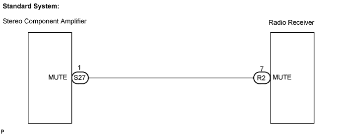
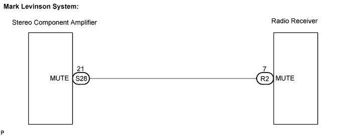
| 1.INSPECT STEREO COMPONENT AMPLIFIER |
 |
Measure the voltage according to the value(s) in the table below.
| Tester connection | Condition | Specified condition |
| MUTE - Body ground | Turn ignition switch to ACC, Audio system is playing → Changing | Above 3.5 V → Below 1 V |
|
| ||||
| OK | ||
| ||
| 2.CHECK HARNESS AND CONNECTOR (RADIO RECEIVER - STEREO COMPONENT AMPLIFIER) |
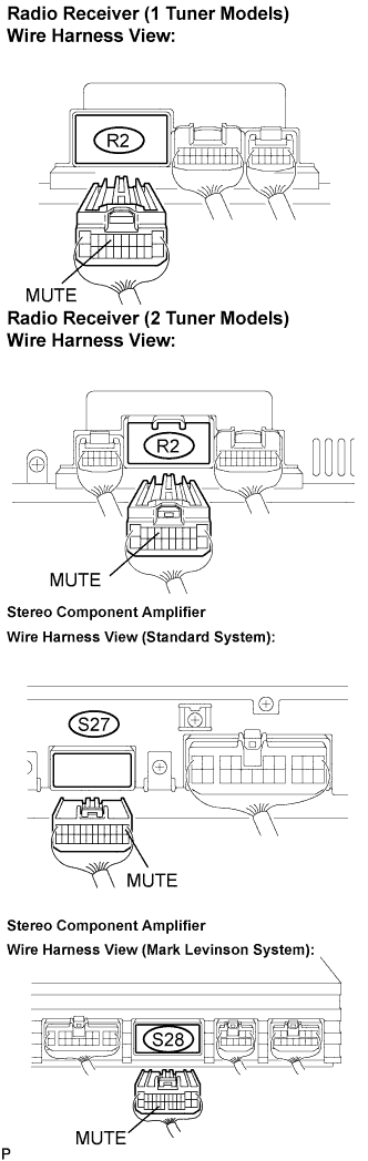 |
Disconnect the connectors from the radio receiver and stereo component amplifier.
Measure the resistance according to the values in the table below.
| Tester connection | Condition | Specified condition |
| MUTE - MUTE | Always | Below 1 Ω |
| MUTE - Body ground | Always | 10 kΩ or higher |
|
| ||||
| OK | |
| 3.INSPECT STEREO COMPONENT AMPLIFIER |
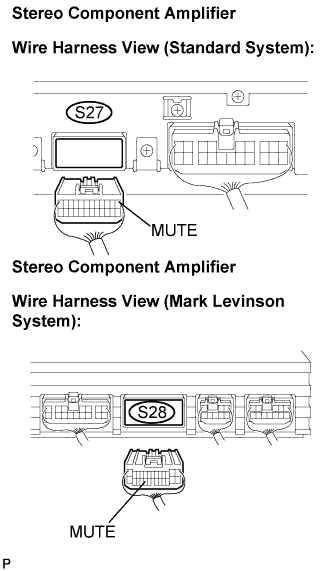 |
Connect the connector to the radio receiver.
Measure the voltage according to the value in the table below.
| Tester connection | Condition | Specified condition |
| MUTE - Body ground | Turn ignition switch to ACC | Above 3.5 V |
|
| ||||
|
| ||||
| NG | ||
| ||
