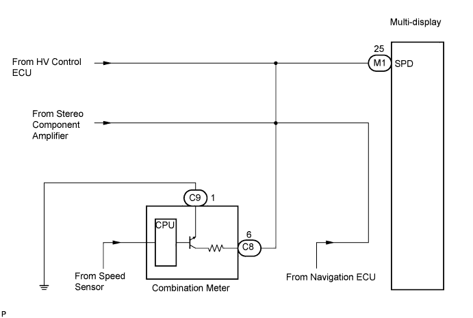
NAVIGATION SYSTEM > Vehicle Speed Signal Circuit between Multi-display and Combination Meter |
| 1.CHECK OPERATION OF SPEEDOMETER |
Drive the vehicle and check if the function of the speedometer in the combination meter is normal.
|
| ||||
| OK | |
| 2.INSPECT MULTI-DISPLAY |
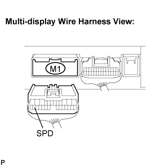 |
Disconnect the multi-display connector M1.
Measure voltage.
Jack up either one of the drive wheels.
Move the shift lever to the neutral position.
Turn the ignition switch to the ON position.
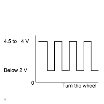 |
Measure the voltage between terminal SPD of the multi-display and body ground when the drive wheels are turned slowly.
|
| ||||
| NG | |
| 3.CHECK HARNESS AND CONNECTOR (COMBINATION METER - MULTI-DISPLAY) |
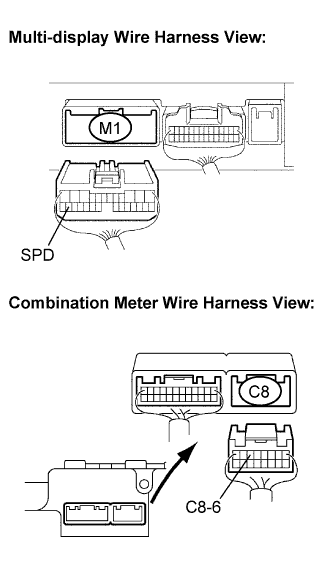 |
Disconnect the multi-display connector M1 and combination meter connector C8.
Measure the resistance according to the value(s) in the table below.
| Tester connection | Condition | Specified condition |
| SPD - C8-6 | Ignition switch OFF | Below 1 Ω |
|
| ||||
| OK | |
| 4.CHECK HARNESS AND CONNECTOR (COMBINATION METER - MULTI-DISPLAY) |
|
Disconnect the multi-display connector M1 and combination meter connector C8.
Measure the resistance according to the value(s) in the table below.
| Tester connection | Condition | Specified condition |
| SPD - Body ground | Ignition switch OFF | 10 kΩ or higher |
|
| ||||
| OK | ||
| ||
