NAVIGATION SYSTEM > Microphone Circuit between Overhead J/B and Multi-display |
| 1.INSPECT MULTI-DISPLAY |
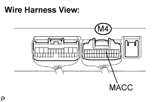 |
Measure the voltage according to the value(s) in the table below.
| Tester connection | Condition | Specified condition |
| MACC - Body ground | Ignition SW ACC | 4 to 6 V |
|
| ||||
| OK | |
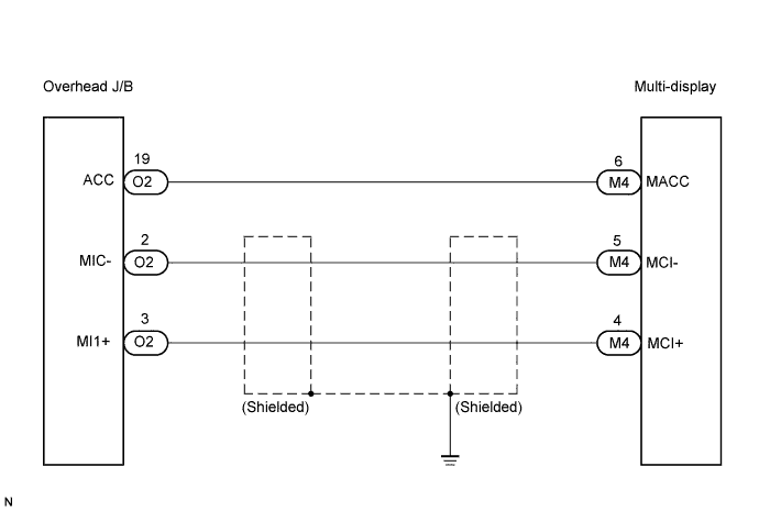
| 2.CHECK HARNESS AND CONNECTOR (OVERHEAD J/B - MULTI-DISPLAY) |
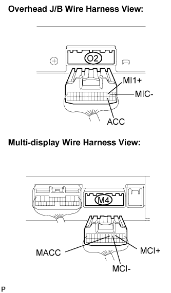 |
Disconnect the overhead J/B connector O2 and multi-display connector M4.
Measure the resistance according to the value(s) in the table below.
| Tester connection | Condition | Specified condition |
| ACC - MACC | Always | Below 1 Ω |
| MI1+ - MCI+ | Always | Below 1 Ω |
| MIC- - MCI- | Always | Below 1 Ω |
| ACC - Body ground | Always | 10 kΩ or higher |
| MI1+ - Body ground | Always | 10 kΩ or higher |
| MIC- - Body ground | Always | 10 kΩ or higher |
|
| ||||
| OK | ||
| ||
