FUEL SENDER GAUGE ASSEMBLY > INSPECTION |
| 1. INSPECT FUEL SENDER GAUGE ASSEMBLY |
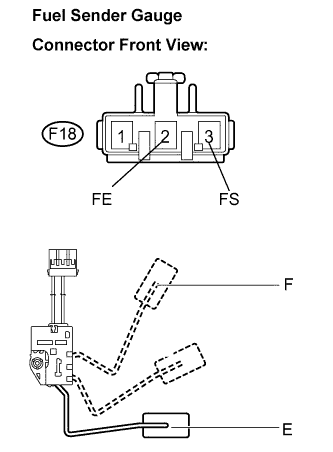 |
Check the operation of the float moving smoothly between F and E.
Disconnect the fuel sender gauge connector.
Remove the fuel sender gauge assembly.
Measure the resistance between the terminals 2 (FE) and 3 (FS) of connector according to the value(s) in the table below.
| Float Level | Resistance (Ω) |
| F | 13.5 to 16.5 |
| E | 405.5 to 414.5 |
