AXLE SYSTEM > SYSTEM DESCRIPTION

for Preparation Click here


GENERAL DESCRIPTION
  1. Under the control of the HV control ECU, this system uses an MGR (Motor Generator Rear) in the rear transaxle to directly drive the rear wheels. According to the driving conditions of the vehicle, the HV control ECU linearly effects distribution control to attain an optimal front-rear torque distribution that provides the drive force required by the vehicle as a whole. Thus, this system realizes a high level of fuel economy and traction performance under various conditions, achieving excellent driving stability.

    Operation of Axle System 
    Control
    Outline
    Start-off
    On a slippery road, the skid control ECU calculates the required total motive force and the torque distribution between the front and rear wheels, and transmits the signals to the HV control ECU. Upon receiving these signals, the HV control ECU appropriately drives the front and rear wheels, in order to achieve traction performance while ensuring driving stability.
    Normal Driving
    1. The system stops the driving of the rear wheels during normal driving to ensure fuel economy performance.
    2. If the vehicle is being driven on a slippery road, accelerating, or making a tight turn, the skid control ECU detects the conditions of the vehicle based on the signals provided by the sensors. Then, the skid control ECU calculates the required total motive force and the torque distribution between the front and rear wheels, and transmits the signals to the HV control ECU. Upon receiving these signals, the HV control ECU appropriately drives the front and rear wheels, in order to achieve traction performance while ensuring driving stability.
    Decelerating
    When the vehicle is decelerating, the kinetic energy is recovered from the front and rear wheels, which is converted into electrical energy, and used for recharging the HV battery by means of MG2 and MGR. This contributes to fuel economy performance.


OPERATION DESCRIPTION
  1. Start-off

    1. The HV control ECU calculates the required motive force based on the amount of effort applied to the accelerator pedal by the driver and the signals from the sensors. Then, the HV control ECU transmits the required motive force and the shift position signal to the skid control ECU.
    2. The skid control ECU determines that the vehicle is in the start-off state based on the signals from the speed sensors, steering angle sensor, and the yawrate & deceleration sensor. Then, the skid control ECU calculates the torque distribution between the front and rear wheels based on the foregoing signals, the required motive force and the shift position signal from the HV control ECU, and transmits them to the HV control ECU.
    3. Upon receiving the signals from the skid control ECU, the HV control ECU controls the motive forces of MG2 and MGR, in order to achieve traction performance while ensuring driving stability.

    4. The HV control ECU constantly monitors the SOC (state of charge) of the HV battery. Thus, it decides whether to use the electrical power of the HV battery to drive MG2 and MGR, to use the electrical power generated by MG1 to drive MG2 and MGR, or to use both electrical powers.


      C107418E01

  2. Normal Driving

    1. The system stops the driving of the rear wheels during normal driving, to ensure fuel economy performance.
    2. If the vehicle is being driven on a slippery road surface, accelerating, or making a tight turn, the skid control ECU detects the conditions of the vehicle based on the signals provided by the speed sensors, steering angle sensor, and the yawrate & deceleration sensor. Then, the skid control ECU calculates the torque distribution between the front and rear wheels, and transmits the signals to the HV control ECU.
    3. Upon receiving the signals from the skid control ECU, the HV control ECU controls the motive forces of the engine, MG2, and MGR, in order to achieve traction performance while ensuring driving stability.

    4. The HV control ECU constantly monitors the SOC (state of charge) of the HV battery. Thus, it decides whether to use the electrical power of the HV battery to drive MG2 and MGR, to use the electrical power generated by MG1 to drive MG2 and MGR, or to use both types of electrical power.


      C107419E01

  3. Decelerating

    1. The HV control ECU determines that the vehicle is decelerating by the required motive force and the shift position signal, and calculates the torque distribution for the front and rear wheels.

    2. Based on the front and rear wheel torque distribution values that have been calculated, the HV control ECU determines the ratio for operating the regenerative brakes of the MG2 and MGR. According to this ratio, the MG2 and MGR charge the HV battery. By converting the kinetic energy of the vehicle into electrical energy and recharging it in the HV battery, this system contributes to enhancing fuel economy.


      C107420E01


FAIL-SAFE FUNCTION (Click here)
If 4WD driving is prohibited due to a malfunction in the vehicle system, "CHECK AWD SYSTEM" will be displayed on the multi-information display in the combination meter assembly, and operations of the rear transaxle will be prohibited.
C107422

DATA LIST (Click here)
By referring to the Data List displayed on the intelligent tester, the value and status of the switch, sensor, ECU, etc. can be read without removing parts. Reading Data List as the first step in troubleshooting is one way to shorten labor time.

ACTIVE TEST (Click here)
Performing the Active Test using the intelligent tester allows the relay, actuator, etc. to operate without removing parts removal. Performing the Active Test as the first step in troubleshooting is one way to shorten labor time. It is possible to display the Data List during the Active Test.

FUNCTION OF COMPONENTS
The table below describes the functions of the main components of the axle system.

Components
Function
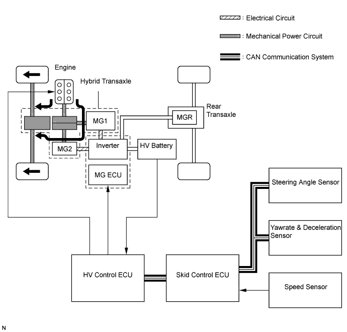
Engine and Hybrid Transaxle
The motive forces of MG2 that is built into the hybrid transaxle and the engine are combined to drive the front wheels.
Rear Transaxle
The motive force of MGR is built into and transmitted to drive the rear wheels.
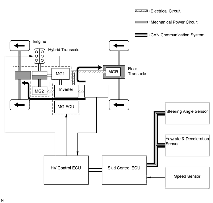
Skid Control ECU
  1. Detects the conditions of the vehicle based on the signals that are input from the sensors and the HV control ECU, calculates the required total motive force and the torque distribution between the front and rear wheels, and transmits the signals to the HV control ECU.
  2. If the skid control ECU detects a failure in the system, it transmits a request to the HV control ECU to display a AWD warning on the multi-information display in the combination meter assembly.
HV Control ECU
  1. Calculates the required motive force based on the amount of effort applied to the accelerator pedal by the driver and the signals from the sensors. Then, the HV control ECU transmits the required motive force and the shift position signal to the skid control ECU.
  2. The HV control ECU controls the engine, MG2, and MGR based on the required total motive force and the torque distribution between the front and rear wheels, which is transmitted by the skid control ECU, in order to appropriately control the motive force.
Speed Sensor
(FL, FR, RL, RR)
Detects the speed of each wheel, and transmits this signal to the skid control ECU.
Steering Angle Sensor
Detects the steering direction and the angle of the steering wheel, and transmits this signal to the skid control ECU.
Yawrate & Deceleration Sensor
Detects the vehicle's acceleration in the forward, rearward, and lateral directions, and sends these signals to the skid control ECU.
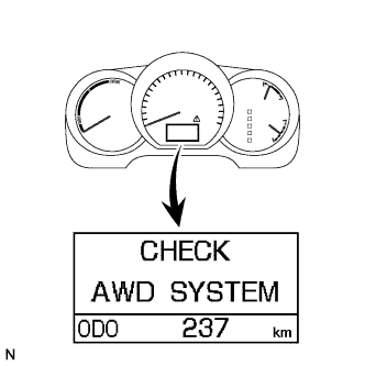
AWD Warning
(Multi-Information Display)
Displayed on the multi-information display in the combination meter assembly in accordance with the illumination request received from the HV control ECU, in order to inform the driver. At the same time, the master warning light illuminates and the buzzer sounds.
MG1
Driven by the engine and generates high-voltage electricity in order to operate MG2 or charge the HV battery. Also functions as a starter to start the engine.
MG2
Driven by electrical power from MG1 or the HV battery and generates a motive force for the front wheels.
MGR
Driven by the electrical power from the HV battery and generates a motive force for the rear wheels.
Accelerator Pedal Position Sensor
Converts the accelerator pedal position into an electrical signal and outputs it to the HV control ECU.
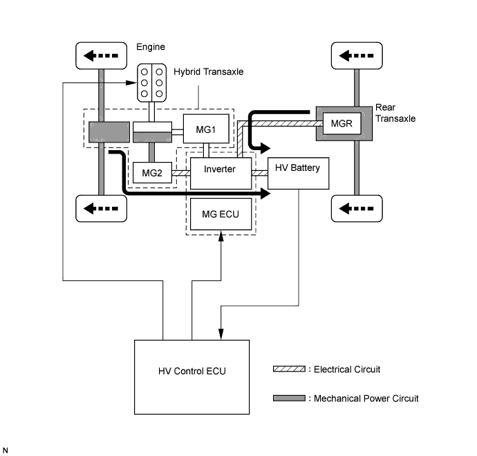
Inverter Assembly
Converts the high-voltage DC (HV battery) into AC (MG1 and MG2) and vice versa (Converts AC into DC).
Drops the maximum voltage of DC 288 V into DC12 V in order to supply electricity to body electrical components, as well as to recharge the auxiliary battery (DC 12 V).
Park/Neutral Position Switch
Converts the shift position into an electrical signal and outputs it to the HV control ECU.