AXLE SYSTEM > DIAGNOSIS SYSTEM

for Preparation Click here


DIAGNOSIS SYSTEM


    C052361E76
  1. Inspect the battery voltage.
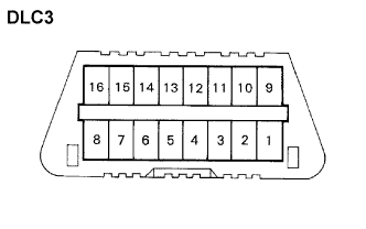
    Voltage:
    11 to 14 V

    If the voltage is below 11 V, recharge the battery before proceeding.

  2. Check the DLC3.
    The skid control ECU and HV control ECU use CAN and the ISO 9141-2 (Euro-OBD) as it communication protocol. The terminal arrangement of the DLC3 complies with ISO 15031-3 and matches the ISO 9141-2 format.
    Verify the conditions listed in the table below.

    Symbols (Teminal No.)
    Terminal Description
    Condition
    Specified condition
    SIL (7) - SG (5)
    Bus "+" line
    During transmission
    Pulse generation
    CG (4) - Body ground
    Chassis ground
    Always
    Below 1 Ω
    SG (5) - Body ground
    Signal ground
    Always
    Below 1 Ω
    BAT (16) - Body ground
    Battery positive
    Always
    11 to 14 V
    CANH (6) - CANL (14)
    HIGH-level CAN bus line
    Ignition switch off
    54 to 67 Ω
    CANH (6) - Battery positive
    HIGH-level CAN bus line
    Ignition switch off
    1 MΩ or higher
    CANH (6) - CG (4)
    HIGH-level CAN bus line
    Ignition switch off
    3 kΩ or higher
    CANL (14) - Battery positive
    LOW-level CAN bus line
    Ignition switch off
    1 MΩ or higher
    CANL (14) - CG (4)
    LOW-level CAN bus line
    Ignition switch off
    3 kΩ or higher

    HINT:
    If the display shows a communication error message when the cable of the intelligent tester is connected to the DLC3, the ignition switch is turned to the ON position and the intelligent tester is operated, there is a problem on either the vehicle side or the tester side.
    1. If communication is normal when the tool is connected to another vehicle, inspect the DLC3 on the original vehicle.
    2. If communication is still not possible when the tester is connected to another vehicle, the problem is probably in the tester itself. Consult the Service Department listed in the tester operator's manual.
    3. If communication is still not possible after the above procedure has been completed, the problem is probably in the DLC3. For the inspection procedure of the DLC3.


  3. C107422E01
  4. Diagnosis system

    1. If the HV control ECU detects that its function to communicate with the skid control ECU fails, or a function that is related to MGR fails, the ECU performs a diagnosis and memorizes the failed sections. Furthermore, the HV control ECU transmits the AWD warning illumination request signal to the combination meter assembly (meter CPU). Then, the combination meter assembly (meter CPU) displays the AWD warning on the multi-information display in the combination meter assembly to inform the driver. Furthermore, the master warning light illuminates and the buzzer sounds simultaneously.
    2. If the skid control ECU detects a failure in the vehicle stability control system, the ECU performs a diagnosis and memorizes the failed sections. Furthermore, the skid control ECU transmits the AWD warning illumination request signal to the HV control ECU. The HV control ECU transmits this signal to the combination meter assembly (meter CPU). Then, the combination meter assembly (meter CPU) displays the AWD warning on the multi-information display in the combination meter assembly to inform the driver. Furthermore, the master warning light illuminates and the buzzer sounds simultaneously.