POWER BACK DOOR SYSTEM > Back Door Lock Latch Switch Circuit |
| 1.INSPECT BACK DOOR LOCK ASSEMBLY |
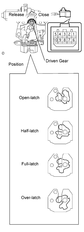 |
Remove the back door lock assembly.
Measure the resistance according to the value(s) in the table below.
| Tester Connection | Door Lock Latch Position | Specified Condition |
| 2 - 4 | Open-latch | 10 kΩ or higher |
| 2 - 4 | Half-latch | 10 kΩ or higher |
| 2 - 4 | Full-latch | 10 kΩ or higher |
| 2 - 4 | Over-latch | Below 1 Ω |
| Tester Connection | Door Lock Latch Position | Specified Condition |
| 3 - 4 | Open-latch | Below 1 Ω |
| 3 - 4 | Half-latch | 10 kΩ or higher |
| 3 - 4 | Full-latch | 10 kΩ or higher |
| 3 - 4 | Over-latch | 10 kΩ or higher |
|
| ||||
| OK | |
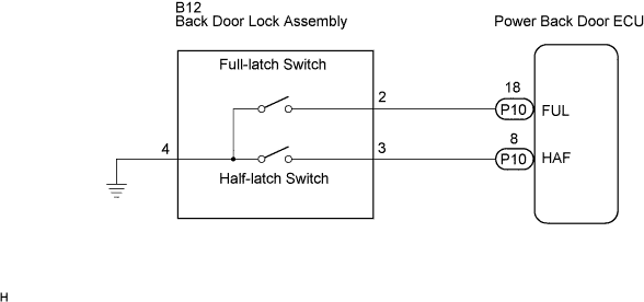
| 2.CHECK WIRE HARNESS (BACK DOOR LOCK ASSEMBLY - POWER BACK DOOR ECU) |
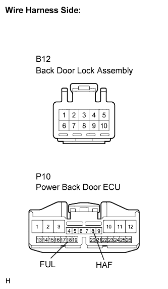 |
Disconnect the back door lock assembly connector.
Disconnect the power back door ECU connector.
Measure the resistance according to the value(s) in the table below.
| Tester Connection | Condition | Specified Condition |
| B12-2 - P10-18 (FUL) | Always | Below 1 Ω |
| B12-3 - P10-8 (HAF) | Always | Below 1 Ω |
| B12-4 - Body ground | Always | Below 1 Ω |
|
| ||||
| OK | ||
| ||
