BRAKE PEDAL STROKE SENSOR > INSTALLATION |
| 1. INSTALL BRAKE PEDAL STROKE SENSOR ASSEMBLY |
New brake pedal stroke sensor assembly:
Install a new brake pedal stroke sensor assembly with the 2 bolts.
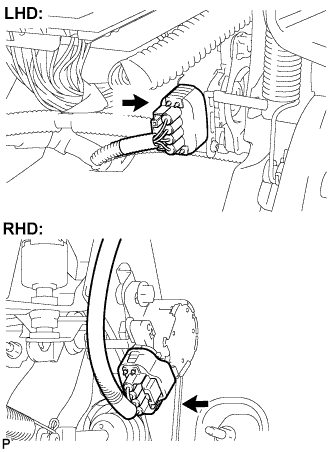
Strongly depress the brake pedal to break the brake pedal stroke sensor assembly lever set pin.
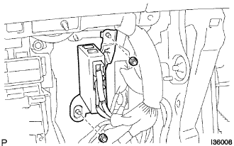
Remove the broken lever set pin.
Connect the brake pedal stroke sensor assembly connector.
Reuse of brake pedal stroke sensor assembly:
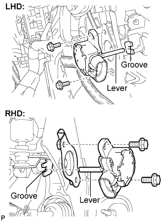 |
Temporarily install the brake pedal stroke sensor assembly with the 2 bolts.
 |
Connect the connector to the brake pedal stroke sensor assembly.
Connect the cable to the negative battery terminal.
Connect the intelligent tester to the DLC3.
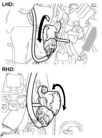 |
Turn the ignition switch to the ON position. Reading the stroke sensor 1 value in the data list shown on the tester screen, turn the stroke sensor slowly to the right and left to adjust the value to the standard voltage.
Fully tighten the 2 bolts.
| 2. DISCONNECT CABLE FROM NEGATIVE BATTERY TERMINAL |
| 3. INSTALL AIR CONDITIONER AMPLIFIER ASSEMBLY (for RHD) |
 |
Install the air conditioner amplifier assembly with the 2 nuts.
| 4. INSTALL DRIVER SIDE KNEE AIRBAG ASSEMBLY |
Install the driver side knee airbag assembly with the 4 bolts.
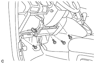 |
Connect the connector to the driver side knee airbag assembly.
| 5. INSTALL INSTRUMENT PANEL FINISH PANEL SUB-ASSEMBLY LOWER |
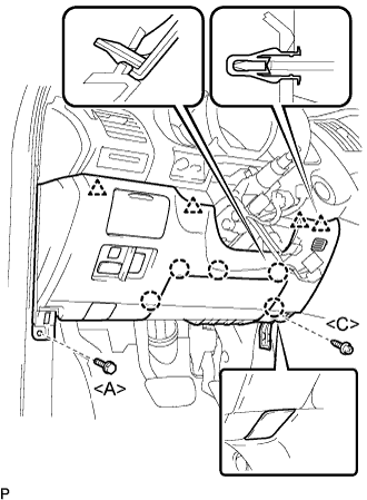 |
Connect the connectors.
Engage the 5 claws and the 4 clips.
Connect the hood lock control cable assembly.
Install the bolt <A>, the screw <C>, and the instrument panel finish panel sub-assembly lower.
| 6. INSTALL COWL SIDE TRIM SUB-ASSEMBLY LH (for LHD) |
| 7. INSTALL COWL SIDE TRIM SUB-ASSEMBLY RH (for RHD) |
| 8. INSTALL FRONT DOOR SCUFF PLATE LH (for LHD) |
| 9. INSTALL FRONT DOOR SCUFF PLATE RH (for RHD) |
| 10. CONNECT CABLE TO NEGATIVE BATTERY TERMINAL |
| 11. CHECK AND CLEAR DTC |
| 12. INSPECT SRS WARNING LIGHT |
| 13. PERFORM LINEAR VALVE OFFSET LEARNING |
When the brake pedal stroke sensor is replaced, perform linear valve offset learning.
(Click here)
| 14. PERFORM INITIALIZATION |
