HYBRID CONTROL SYSTEM > DIAGNOSIS SYSTEM

for Preparation Click here


DESCRIPTION


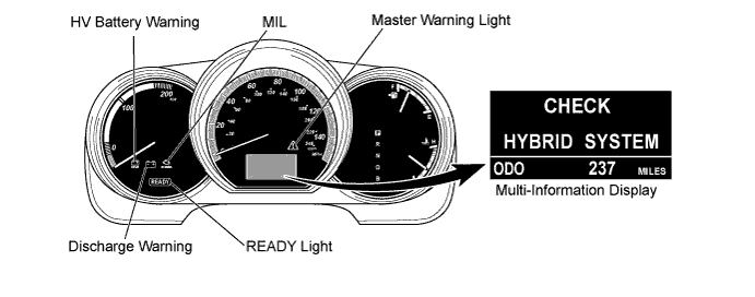
  1. The HV control ECU has a self-diagnosis system. If the computer, hybrid vehicle control system or the components are not working properly, the ECU carries out a diagnosis to detect the malfunction, and illuminates the master warning light in the combination meter together with any of the indicators on the multi-information display, the HV system warning, the HV battery warning or the discharge warning.


    A111629E02

    HINT:
    The master warning light illuminates when THS II fails and it blinks when in inspection mode.


  2. E109221E03
  3. Description for Euro-OBD (European spec.)
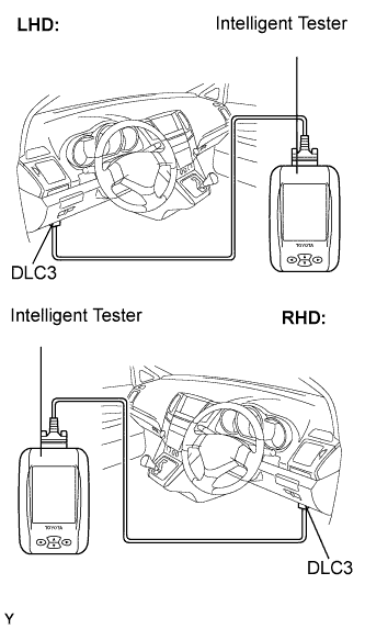
    1. When troubleshooting Euro-OBD vehicles, the only difference from the usual troubleshooting procedure is that you need to connect the OBD scan tool complying with ISO 15031-4 or the intelligent tester to the vehicle, and read various data output from the vehicle's ECUs.
    2. Euro-OBD regulations require that the vehicle's on-board computer illuminates the MIL in the instrument panel when the computer detects malfunction in: 1) the emission control systems/components, or 2) the powertrain control components (which affect vehicle emissions), or 3) the computers. In addition, the applicable Diagnostic Trouble Codes (DTCs) prescribed by ISO 15031-4 are recorded in the HV control ECU memory (Click here).
      If the malfunction does not recur in 3 consecutive trips, the MIL will go off automatically. However the DTCs remain recorded in the HV control ECU memory.
    3. To check the DTCs, connect the intelligent tester or OBD scan tool to the Data Link Connector 3 (DLC3) of the vehicle. The intelligent tester or OBD scan tool also enables you to erase the DTCs and check the freeze frame data and various forms of the HV battery system data (for operating instructions, refer to their respective instruction manuals). The DTCs include ISO controlled codes and manufacturer controlled codes. ISO controlled codes must be set as prescribed by the ISO, while manufacturer controlled codes can be set by a manufacturer within the prescribed limits (Click here).
    4. Freeze frame data:
      The freeze frame data records the driving condition when malfunction is detected. When troubleshooting, it can help determine if the vehicle was running, braked, stopped, or reversed.

If the malfunction does not recur in 3 consecutive trips, the MIL will go off automatically. However the DTCs remain recorded in the HV control ECU memory.

CHECK DLC3
  1. The battery ECU uses the ISO 9141-2 (Euro-OBD) for communication protocol. The terminal arrangement of the DLC3 complies with ISO 15031-03 and matches the ISO 9141-2 / ISO 14230 format.
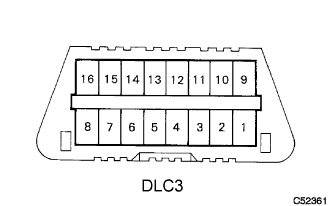
C052361E04

Symbol
Terminal No.
Name
Reference Terminal
Result
Condition
SIL
7
Bus "+" line
5 - Signal ground
Pulse generation
Always
CG
4
Chassis ground
Body ground
1 Ω or less
Always
SG
5
Signal ground
Body ground
1 Ω or less
Always
BATT
16
Battery positive
Body ground
11 to 14 V
Ignition switch OFF
CANH
6
HIGH-level CAN bus line
14 - LOW-level CAN bus line
54 to 69 Ω
Ignition switch OFF
CANH
6
HIGH-level CAN bus line
14 - Battery positive
1 MΩ or higher
Ignition switch OFF
CANH
6
HIGH-level CAN bus line
4 - Chassis ground
1 kΩ or higher
Ignition switch OFF
CANL
14
LOW-level CAN bus line
16 - Battery positive
1 MΩ or higher
Ignition switch OFF
CANL
14
LOW-level CAN bus line
4 - Chassis ground
1 kΩ or higher
Ignition switch OFF

HINT:
If the display shows a communication error message when you have connected the cable of the intelligent tester to the DLC3, turned the ignition switch to the ON position and operated the tester, there is a problem on the vehicle side or tester side.
  1. If communication is normal when the tester is connected to another vehicle, inspect the DLC3 on the original vehicle.
  2. If communication is still not possible when the tester is connected to another vehicle, the problem is probably in the tester itself, so consult the Service Department listed in its instruction manual.


INSPECT AUXILIARY BATTERY
  1. Measure the voltage of the auxiliary battery.

    Voltage:
    10 to 14 V

  2. Inspect the auxiliary battery, fuses, fusible links, wiring harness, connectors and ground.


CHECK MIL
  1. The MIL illuminates when the ignition switch is turned to the ON position and the "READY" light is off.
    If the MIL is not illuminated, troubleshoot the MIL circuit (Click here).

  2. When the "READY" light turns on, the MIL should turn off. If the MIL remains on, the diagnosis system has detected a malfunction or abnormality in the system.