Item
| Outline
|
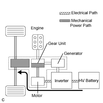
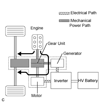
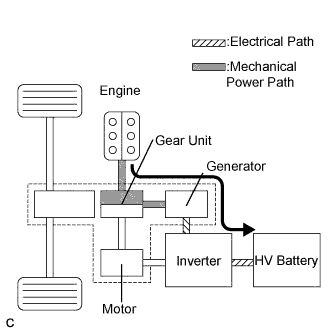
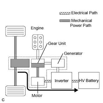
Hybrid Transaxle
| Generator
| - The generator, which is driven by the engine, generates high-voltage electricity in order to operate the Motor or charge the HV battery. Also, it functions as a starter to start the engine.
- The generator operates so that the gear ratio of the power split planetary gear unit will optimally suit the driving conditions of the vehicle.
|
Motor
| - Driven by electrical power from the Generator or the HV battery, and generates motive force for the front wheels.
- During braking, or when the accelerator pedal is not depressed, it generates electricity to recharge the HV battery (Regenerative brake control).
|
Compound Gear Unit
| Power Split Planetary Gear
| Distributes the engine's drive force as appropriate to directly drive the vehicle as well as the generator.
|
Motor Speed Reduction Planetary Gear
| Located between the Motor and the power split planetary gear, the motor speed reduction planetary gear reduces the rotational speed of the Motor in accordance with the characteristics of the planetary gear, in order to increase torque.
|
Rear Transaxle*
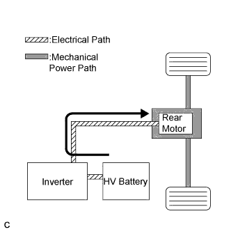
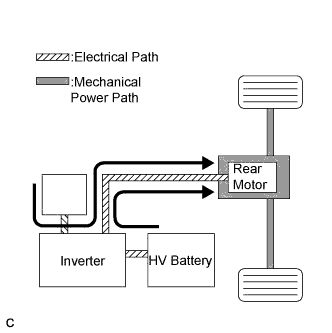
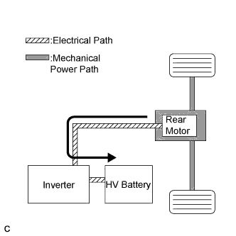
| Rear Motor
| - Driven by electrical power from the Generator or the HV battery, and generates motive force for the rear wheels.
- During braking, or when the accelerator pedal is not depressed, it generates electricity to recharge the HV battery (Regenerative brake control).
|
HV Battery
| - Supplies electrical power to the Generator, Motor, and Rear Motor* in accordance with the driving conditions of the vehicle.
- Is recharged by the Generator, Motor, and Rear Motor* in accordance with the SOC and the driving conditions of the vehicle.
|
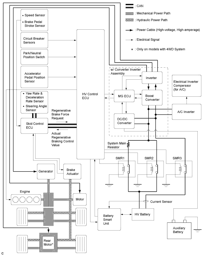
w/ Converter Inverter Assembly
| A device that converts the high-voltage DC (HV battery) into AC (Generator and Motor) and vice versa (Converts AC into DC).
|
| Boost Converter
| Boosts the maximum voltage of the HV battery from DC 288 V to DC 650 V and vice versa (drops DC 650 V to DC 288 V).
|
DC/DC Converter
| Drops the maximum voltage of DC 288 V into DC 12 V in order to supply electricity to body electrical components, as well as to recharge the auxiliary battery (DC 12 V).
|
MG ECU
| - Controls the inverter and boost converter in accordance with the signals received from the HV control ECU, thus driving the Generator, Motor, or Rear Motor or causing them to generate electricity.
- Controls the DC/DC converter in accordance with the signals received from the HV control ECU.
|
HV Control ECU
| Effects comprehensive control of the THS-II system.
- Information from each sensor as well as from the ECU (battery smart unit, skid control ECU, and EPS ECU) is received, and based on this information, the required torque and output power is calculated. The HV control ECU sends the calculated result to the inverter assembly and skid control ECU.
- Activates the ETCS-i (Electronic Throttle Control System-intelligent) in accordance with the target engine speed and required engine motive force.
- Monitors the charging condition of the HV battery.
- Controls the cooling fan of the HV battery.
|
Battery Smart Unit
| - Monitors the conditions of the HV battery and transmits this information to the HV control ECU.
- Monitors the fault current of the HV battery.
|
Skid Control ECU
| - During braking, it calculates the regenerative brake force that is required for control and transmits it to the HV control ECU.
- Calculates the motive force that is required for control during the operation of TRAC or VSC and transmits it to the HV control ECU.
- Transmits a front and rear wheel torque distribution request to the HV control ECU for the purpose of 4WD system control.*
|
Accelerator Pedal Position Sensor
| Converts the accelerator pedal position into an electrical signal and outputs it to the HV control ECU.
|
Park/Neutral Position Switch
| Converts the shift position into an electrical signal and outputs it to the HV control ECU.
|
HV Relay Assembly
| Connects and disconnects the high-voltage power circuit between the battery and the inverter assembly, through the use of a signal from the HV control ECU.
|
Interlock Switch
(for Inverter Cover and Service Plug Grip)
| Verifies that the cover of both the inverter and the service plug grip have been installed.
|
Circuit Breaker Sensor
| Detects the impact that is applied to the vehicle during a collision and transmits a signal to the HV control ECU. Upon receiving this signal, the HV control ECU operates the HV relay assembly to shut down the power supply.
|
Service Plug Grip
| Shuts off the high-voltage circuit of the HV battery when this service plug grip is removed for vehicle inspection or maintenance.
|