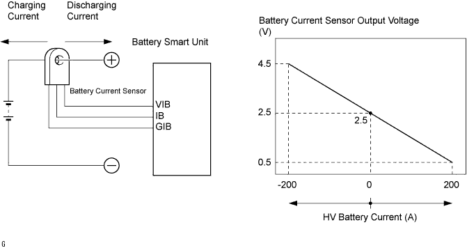
DTC    P0AC0    Hybrid Battery Pack Current Sensor Circuit Range/Performance

for Preparation Click here


DESCRIPTION


  1. The battery current sensor, which is mounted on the negative cable side of the HV battery assembly, detects the amperage that flows into the HV battery. The battery smart unit inputs a voltage, which varies between 0 and 5 V in proportion to the amperage, into the IB terminal from the battery current sensor. An output voltage of the battery current sensor below 2.5 V indicates that the HV battery is being charged, and above 2.5 V indicates that the HV battery is being discharged. The HV control ECU determines the charging and discharging amperage of the HV battery based on the signals that are input to its IB terminal from the battery smart unit, and calculates the SOC (state of charge) of the HV battery through the accumulated amperage.


    A108798E01


DTC No.
DTC Detection Condition
Trouble Area
P0AC0
When the battery current sensor is abnormal (1 or 2 trip detection)
  1. HV relay assembly (Battery current sensor)
  2. Battery smart unit

MONITOR DESCRIPTION

If the battery smart unit detects a malfunction in the battery current sensor, the HV control ECU illuminates the MIL and sets a DTC.

WIRING DIAGRAM


A088713E03


INSPECTION PROCEDURE

CAUTION:
  1. Before inspecting the high-voltage system, take safety precautions to prevent electrical shocks, such as wearing insulated gloves and removing the service plug grip. After removing the service plug grip, put it in your pocket to prevent other technicians from reconnecting it while you are working on the high-voltage system.
  2. After disconnecting the service plug grip, wait for at least 5 minutes before touching any of the high-voltage connectors or terminals.

HINT:
At least 5 minutes is required to discharge the high-voltage capacitor inside the w/ converter inverter assembly.

1.READ OUTPUT DTC (DTC P0A1F IS OUTPUT)
  1. Connect the intelligent tester to the DLC3.

  1. Turn the ignition switch to the ON position.

  1. Select the following menu items: Powertrain / Hybrid Control / DTC.

  1. Read output DTCs. (Click here)

    Result:
    DTC P0A1F is output.


YES
REPLACE BATTERY SMART UNIT
NO


2.REPLACE HV RELAY ASSEMBLY
  1. Replace the HV relay assembly. (Click here)


NEXT


3.CLEAR DTC
  1. Install the battery cover. (Click here)

  1. Connect the intelligent tester to the DLC3.

  1. Turn the ignition switch to the ON position.

  1. Select the following menu items: Powertrain / Hybrid Control / DTC / Clear.

  1. Perform a driving test.

    HINT:
    Turn the ignition switch off and perform a driving test again after the first driving test for 2 trip detection.


NEXT


4.READ OUTPUT DTC (DTC IS NOT OUTPUT AGAIN)
  1. Connect the intelligent tester to the DLC3.

  1. Turn the ignition switch to the ON position.

  1. Select the following menu items: Powertrain / Hybrid Control / DTC.

  1. Read output DTCs. (Click here)

    Result:
    One or several of DTCs P0AC0, P0ABF, P0AC1, and P0AC2 will be output again.


YES
REPLACE BATTERY SMART UNIT
NO

SYSTEM OK