DTC P0A9C Hybrid Battery Temperature Sensor "A" |
DTC P0A9D Hybrid Battery Temperature Sensor "A" Circuit Low |
DTC P0A9E Hybrid Battery Temperature Sensor "A" Circuit High |
DTC P0AC5 Hybrid Battery Temperature Sensor "B" Circuit |
DTC P0AC7 Hybrid Battery Temperature Sensor "B" Circuit Low |
DTC P0AC8 Hybrid Battery Temperature Sensor "B" Circuit High |
DTC P0ACA Hybrid Battery Temperature Sensor "C" |
DTC P0ACC Hybrid Battery Temperature Sensor "C" Circuit Low |
DTC P0ACD Hybrid Battery Temperature Sensor "C" Circuit High |
| DTC No. | DTC Detection Condition | Trouble Area |
| P0A9C P0A9D P0A9E P0AC5 P0AC7 P0AC8 P0ACA P0ACC P0ACD |
|
|
| Temperature Displayed | Malfunction |
| Below -45°C | Open or +B short circuit |
| 95°C or more | GND short circuit |
| 1.READ OUTPUT DTC (DTC P0A1F IS OUTPUT) |
Connect the intelligent tester to the DLC3.
Turn the ignition switch to the ON position.
Select the following menu items: Powertrain / Hybrid Control / DTC.
Read output DTCs. (Click here)
|
| ||||
| NO | |
| 2.CHECK CONNECTION OF BATTERY TEMPERATURE SENSOR CONNECTOR (LOOSENESS AND POOR CONTACT) |
Turn the ignition switch off and remove the service plug grip. (Click here)
Remove the battery cover. (Click here)
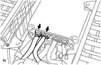 |
Check the connections of the B27 and B28 connectors of the battery smart unit.
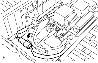 |
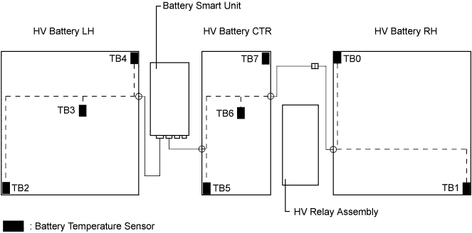
Check the connections of connectors between the battery temperature sensor (No.0) and battery temperature sensor (No.2).
|
| ||||
| OK | |
| 3.CHECK HV BATTERY (BATTERY TEMPERATURE SENSOR) |
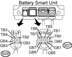 |
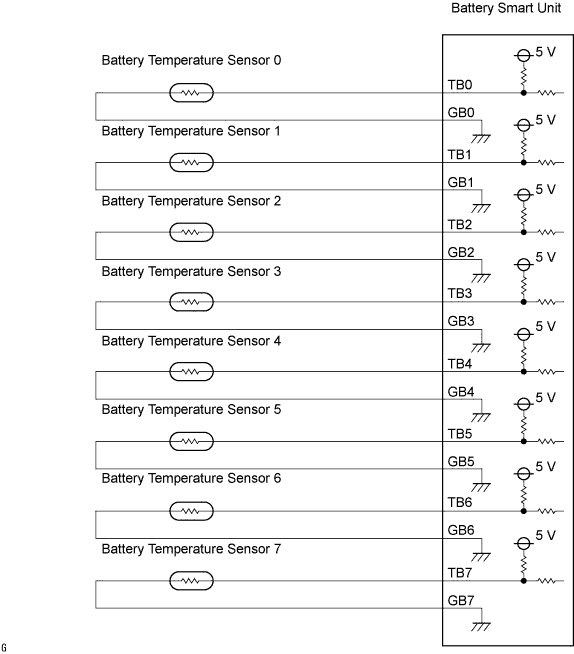
Disconnect the B27 and B28 connectors from the battery smart unit.
Measure the resistance according to the conditions and value(s) in the tables below.
| Tester Connection | Thermistor No. |
| TB0 (B27-1) - GB0 (B27-6) | 0 |
| TB1 (B27-2) - GB1 (B27-7) | 1 |
| TB2 (B28-1) - GB2 (B28-4) | 2 |
| TB3 (B28-2) - GB3 (B28-5) | 3 |
| TB4 (B28-3) - GB4 (B28-6) | 4 |
| TB5 (B27-3) - GB5 (B27-8) | 5 |
| TB6 (B27-4) - GB6 (B27-9) | 6 |
| TB7 (B27-5) - GB7 (B27-10) | 7 |
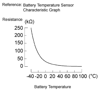
| Thermistor Temperature | Specified Condition (kΩ) |
| 0°C (32°F) | 27.0 to 27.6 |
| 25°C (77°F) | 9.9 to 10.1 |
| 40°C (104°F) | 5.77 to 5.89 |
|
| ||||
| OK | |
| 4.CHECK OUTPUT DTC |
Turn the ignition switch to the ON position.
Select the following menu items: Powertrain / Hybrid Control / DTC.
Check that the output DTCs indicate performance problems.
|
| ||||
| YES | |
| 5.CHECK INSTALLATION OF BATTERY TEMPERATURE SENSOR |
Remove the HV battery with the relevant battery temperature sensor.
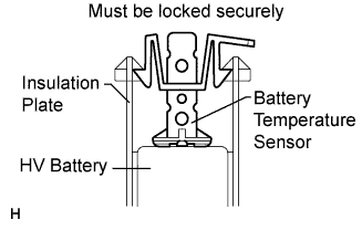 |
Turn over the relevant HV battery and check the installation of the battery temperature sensor.
| Result | Proceed to |
| The battery temperature sensor is installed correctly. | A |
| The claws are damaged. | B |
| The battery temperature sensor is not installed correctly, but the claws are not damaged. | C |
|
| ||||
|
| ||||
| A | ||
| ||
