DTC P0AD0 Hybrid Battery Pack Cooling Fan 3 Performance or Stuck OFF |
| DTC No. | DTC Detection Condition | Trouble Area |
| P0AD0 | When the speed of the battery blower assembly is not within the target range speed (1 trip detection) |
|
| 1.READ OUTPUT DTC |
Connect the intelligent tester to the DLC3.
Turn the ignition switch to the ON position.
Select the following menu items: Powertrain / Hybrid Control / DTC.
Read output DTCs. (Click here)
| DTC output | Proceed to |
| P0AD0 only is output | A |
| P0A1F is output | B |
| Any of P0A84, P0A85, P0A99, P0A9A, P0AD2 and P0AD3 are output | C |
|
| ||||
|
| ||||
| A | |
| 2.CHECK BATTERY COOLING BLOWER ASSEMBLY (NO.2) |
Connect the intelligent tester to the DLC3.
Select the following menu items: Powertrain / Hybrid Control / Data List / VMF Fan Voltage 1 to 3 and Batt Temp 1 to 8.
Perform a driving test and check that there is a malfunction in the VMF Fan Voltage 3 while the battery cooling blower No.2 is operating. (*1)
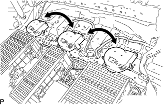 |
Remove the battery cover and replace the battery cooling blower assembly No.2 with the battery cooling blower assembly No.0 or No.1. (Click here)
Install the battery cover. (Click here)
Select the following menu items: Powertrain / Hybrid Control / Data List / VMF Fan Voltage 1 to 3 and / Batt Temp 1 to 8.
Perform a driving test and check that the malfunction in (*1) is reproduced in the battery cooling blower No.0 or No.1.
|
| ||||
| NO | ||
| ||
