DTC P3105 Battery Smart Unit Communication Circuit Malfunction |
| DTC No. | DTC Detection Condition | Trouble Area |
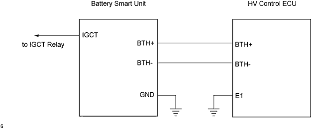
| P3105 | Problem in serial communication between the battery smart unit and HV control ECU (1 trip) | Wire harness or connector HV control ECU Battery smart unit |
| 1.INSPECT HYBRID VEHICLE CONTROL ECU |
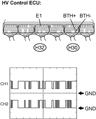 |
Connect the intelligent tester to the HV control ECU terminals specified in the table below, set the tester to the oscilloscope function, and check the waveform.
| Item | Contents |
| Terminal | CH1: BTH+ (H30-19) - E1 (H32-5) CH2: BTH- (H30-30) - E1 (H32-5) |
| Equipment Setting | 2V/DIV, 500μs/DIV |
| Condition | Ignition switch ON |
|
| ||||
| NO | |
| 2.CHECK HARNESS AND CONNECTOR (HV CONTROL ECU - BATTERY PACK WIRE) |
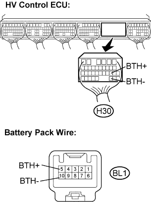
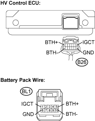
Disconnect the H30 connector from the HV control ECU.
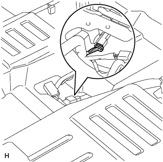 |
Disconnect the BL1 connector shown in the illustration.
 |
Measure the resistance according to the value(s) in the table below.
| Tester Connection | Specified Condition |
| BTH+ (H30-19) - BTH+ (BL1-5) | Below 1 Ω |
| BTH- (H30-30) - BTH- (BL1-10) | Below 1 Ω |
| Tester Connection | Specified Condition |
| BTH+ (H30-19) - Body ground | 10 kΩ or higher |
| BTH- (H30-30) - Body ground | 10 kΩ or higher |
|
| ||||
| OK | |
| 3.CHECK HARNESS AND CONNECTOR (BATTERY PACK WIRE) |
Connect the H30 connector to the HV control ECU.
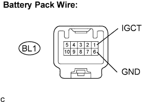 |
Measure the voltage according to the value(s) in the table below when the ignition switch is in the ON position.
| Tester Connection | Specified Condition (V) |
| IGCT (BL1-1) - GND (BL1-6) | 9 to 14 V |
|
| ||||
| OK | |
| 4.INSPECT BATTERY PACK WIRE |
Remove the service plug grip. (Click here)
Remove the battery cover. (Click here)
Disconnect the B26 connector from the battery smart unit.
 |
Measure the resistance according to the value(s) in the table below.
| Tester Connection | Specified Condition |
| BTH+ (B26-7) - BTH+ (BL1-5) | Below 1 Ω |
| BTH- (B26-14) - BTH- (BL1-10) | Below 1 Ω |
| IGCT (B26-1) - IGCT (BL1-1) | Below 1 Ω |
| GND (B26-8) - GND (BL1-6) | Below 1 Ω |
| Tester Connection | Specified Condition |
| BTH+ (B26-7) - Body ground | 10 kΩ or higher |
| BTH- (B26-14) - Body ground | 10 kΩ or higher |
| IGCT (B26-1) - Body ground | 10 kΩ or higher |
| GND (B26-8) - Body ground | 10 kΩ or higher |
|
| ||||
| OK | ||
| ||
