WIPER SWITCH > INSPECTION |
| 1. WINDSHIELD WIPER SWITCH ASSEMBLY |
 |
Check the continuity of windshield wiper switch assembly.
Measure the resistance according to the value(s) in the table below.
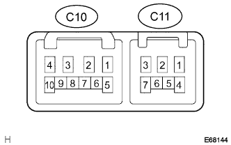
| Switch position | Tester connection | Specified resistance |
| MIST | C10-2 (+B) - C10-3 (+1) | Below 1 Ω |
| OFF | C10-1 (+S) - C10-3 (+1) | Below 1 Ω |
| INT | C10-1 (+S) - C10-3 (+1) | Below 1 Ω |
| LO | C10-2 (+B) - C10-3 (+1) | Below 1 Ω |
| HI | C10-2 (+B) - C10-4 (+2) | Below 1 Ω |
| Switch position | Tester connection | Specified resistance |
| MIST | C10-2 (+B) - C10-3 (+1) | Below 1 Ω |
| OFF | C10-1 (+S) - C10-3 (+1) | Below 1 Ω |
| AUTO | C10-1 (+S) - C10-3 (+1) C10-9 (AUTO) - C10-10 (E) | Below 1 Ω |
| LO | C10-2 (+B) - C10-3 (+1) | Below 1 Ω |
| HI | C10-2 (+B) - C10-4 (+2) | Below 1 Ω |
| Switch position | Tester connection | Specified resistance |
| OFF | - | 10 kΩ or higher |
| INT | C11-2 (EW) - C11-6 (C1R) | Below 1 Ω |
| ON | C11-2 (EW) - C11-7 (+1R) | Below 1 Ω |
| Switch position | Tester connection | Specified resistance |
| OFF | - | 10 kΩ or higher |
| ON | C11-2 (EW) - C11-3 (WF) | Below 1 Ω |
| Switch position | Tester connection | Specified resistance |
| OFF | - | 10 kΩ or higher |
| ON (Rear wiper switch OFF position side) | C11-2 (EW) - C10-5 (WR) | Below 1 Ω |
| ON (Rear wiper switch ON position side) | C11-2 (EW) - C10-5 (WR) C11-2 (EW) - C10-7 (+1R) | Below 1 Ω |
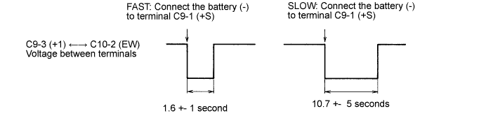
Intermittent Operation Check ( w/o Rain Sensor)
Connect the voltmeter (+) terminal to terminal C10-3 (+1) of the connector and the voltmeter (-) terminal to C11-2 (EW).
Connect the position battery (+) lead to terminal C10-2 (+B) of the connector and the negative battery (-) lead to terminals C11-2 (EW) and C10-1 (+S).
Turn the wiper switch to the INT position.
Connect the position battery (+) lead to the terminal C10-1 (+S) of the connector for 5 seconds.
Connect the negative battery (-) lead to terminal C10-4 (+S) of the connector. Operate the intermittent wiper relay and measure the voltage between terminal C10-3 (+1) and terminal C11-2 (EW).
Front Wiper Operation Check ( w/o Rain Sensor)
Turn the wiper switch to the OFF position.
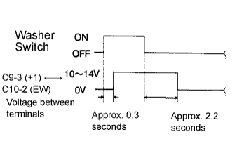 |
Connect the position battery (+) lead to terminal C10-2 (+B) of the connector, the negative battery (-) lead to the terminals C10-1 (+S) and the terminal C11-2 (EW).
Connect the voltmeter (+) terminal to the terminal C10-3 (+1) of the connector and the voltmeter (-) terminal to the terminal C11-2 (EW) of the connector. Turn the washer switch to the ON and OFF position, and measure the voltage between terminal C10-3 (+1) and terminal C11-2 (EW).
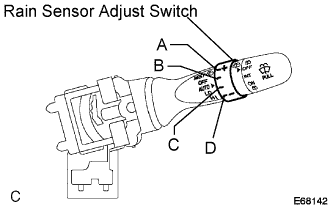 |
Rain Sensor Adjust Switch Operation Check (w/ Rain Sensor)
Measure the resistance according to the value(s) in the table below.
| Tester connection | Condition | Specified condition |
| C10-7 (VR1) - C10-8 (VR2) | A position | Below 10 Ω |
| C10-7 (VR1) - C10-8 (VR2) | B position | 405 to 493 Ω |
| C10-7 (VR1) - C10-8 (VR2) | C position | 1400 to 1700 Ω |
| C10-7 (VR1) - C10-8 (VR2) | Dposition | 2200 to 3200 Ω |
