NAVIGATION SYSTEM > RDS-TMC Signal Circuit between Radio Receiver and Navigation ECU |
| 1.CHECK HARNESS AND CONNECTOR (NAVIGATION ECU - RADIO RECEIVER) |
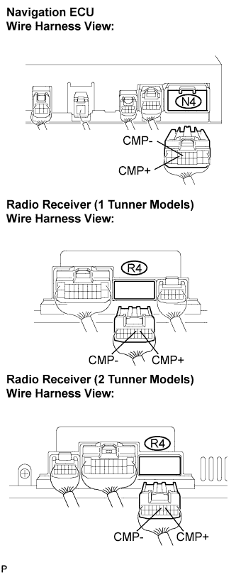 |
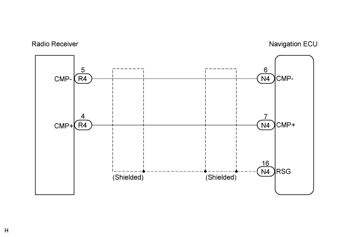
Disconnect the navigation ECU connector N4 and radio receiver connector R4.
Measure the resistance according to the value(s) in the table below.
| Tester connection | Condition | Specified condition |
| CMP+ - CMP+ | Always | Below 1 Ω |
| CMP- - CMP- | Always | Below 1 Ω |
| CMP+ - Body ground | Always | 10 kΩ or higher |
| CMP- - Body ground | Always | 10 kΩ or higher |
|
| ||||
| OK | ||
| ||
