ECU TERMINAL CHART
Symbols
(Terminal No.)
| Wiring Color
| Terminal Description
| Condition
| Standard (V)
|
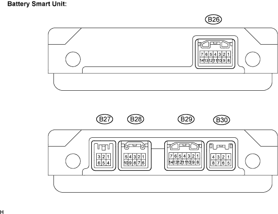
IGCT (B26-1) - GND (B26-8)
| R - W-B
| Control signal
| READY-on state
| 9 to 14
|
VM0 (B26-3) - GND (B26-8)
| L - W-B
| Cooling fan No.0 monitor signal
| Cooling fan No.0 activation
| 0 to 10
|
VM1 (B26-4) - GND (B26-8)
| P - W-B
| Cooling fan No.1 monitor signal
| Cooling fan No.1 activation
| 0 to 10
|
VM2 (B26-5) - GND (B26-8)
| O - W-B
| Cooling fan No.2 monitor signal
| Cooling fan No.2 activation
| 0 to 10
|
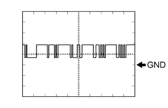
BTH+ (B26-7) - GND (B26-8)
| Y - W-B
| Serial communication
| Ignition switch ON
| Pulse generation
(waveform 1)
|
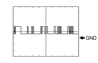
BTH- (B26-14) - GND (B26-8)
| BR - W-B
| ↑
| Ignition switch ON
| Pulse generation
(waveform 2)
|
TB0 (B28-1) - GB0 (B28-6)
| W - W
| HV battery temperature sensor 0
| HV battery temperature: -40 to 90°C (-40 to 194°F)
| 4.8 to 1.0
|
TB1 (B28-2) - GB1 (B28-7)
| L - L
| HV battery temperature sensor 1
| HV battery temperature: -40 to 90°C (-40 to 194°F)
| 4.8 to 1.0
|
TB2 (B27-1) - GB2 (B27-4)
| R - R
| HV battery temperature sensor 2
| HV battery temperature: -40 to 90°C (-40 to 194°F)
| 4.8 to 1.0
|
TB3 (B27-2) - GB3 (B27-5)
| W - W
| HV battery temperature sensor 3
| HV battery temperature: -40 to 90°C (-40 to 194°F)
| 4.8 to 1.0
|
TB4 (B27-3) - GB4 (B27-6)
| G - G
| HV battery temperature sensor 4
| HV battery temperature: -40 to 90°C (-40 to 194°F)
| 4.8 to 1.0
|
TB5 (B28-3) - GB5 (B28-8)
| R - R
| HV battery temperature sensor 5
| HV battery temperature: -40 to 90°C (-40 to 194°F)
| 4.8 to 1.0
|
TB6 (B28-4) - GB6 (B28-9)
| O - O
| HV battery temperature sensor 6
| HV battery temperature: -40 to 90°C (-40 to 194°F)
| 4.8 to 1.0
|
TB7 (B28-5) - GB7 (B28-10)
| G - G
| HV battery temperature sensor 7
| HV battery temperature: -40 to 90°C (-40 to 194°F)
| 4.8 to 1.0
|
VIB (B26-10) - GIB (B26-12)
| Y-B - V
| Power source for battery current sensor
| Ignition switch ON
| 4.5 to 5.5
|
IB( B26-11) - GIB (B26-12)
| BR-B - V
| Battery current sensor
| READY-on state
| 0.5 to 4.5
|
GND (B26-8) - Body ground
| W-B - body ground
| Ground
| Always (continuity check)
| Continuity.
(Below 6 Ω)
|