DTC P0560-117 System Voltage |
| DTC No. | INF Code | DTC Detection Condition | Trouble Area |
| P0560 | 117 | HV control ECU back-up power source circuit malfunction |
|
| 1.CHECK CONNECTION CONDITION OF HYBRID VEHICLE CONTROL ECU CONNECTOR (LOOSENESS AND POOR CONTACT) |
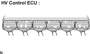 |
Check the connections of all HV control ECU connectors.
|
| ||||
| OK | |
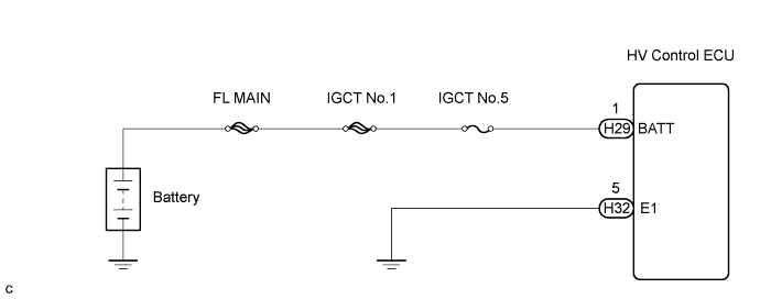
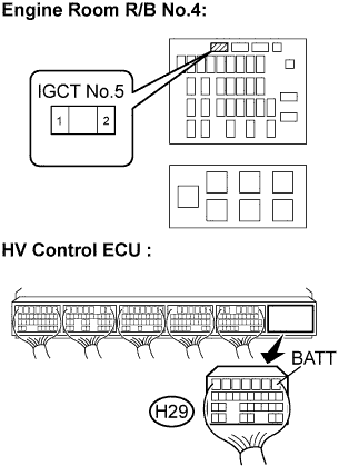
| 2.CHECK HARNESS AND CONNECTOR (HV CONTROL ECU - IGCT NO.5 FUSE) |
Turn the ignition switch OFF.
Remove the IGCT No.5 fuse from the engine room R/B No.4.
Disconnect the H29 connector from the HV control ECU.
 |
Measure the resistance according to the value(s) in the table below.
| Tester Connection | Specified Condition |
| BATT (H29-1) - Engine room R/B No.4 IGCT No.5 fuse terminal 2 | Below 1 Ω |
| Tester Connection | Specified Condition |
| BATT (H29-1) or Engine room R/B No.4 IGCT No.5 fuse terminal 2 - Body ground | 10 kΩ or more |
|
| ||||
| OK | |
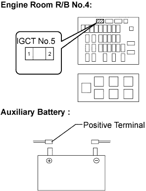
| 3.CHECK HARNESS AND CONNECTOR (IGCT NO.5 FUSE - BATTEY POSITIVE TERMINAL) |
Disconnect the positive and negative cables from the auxiliary battery.
 |
Measure the resistance according to the value(s) in the table below.
| Tester Connection | Specified Condition |
| Engine room R/B No.4 IGCT No.5 fuse terminal 1 - Battery positive terminal | Below 1 Ω |
| Tester Connection | Specified Condition |
| Engine room R/B No.4 IGCT No.5 fuse terminal 1 - Body ground | 10 kΩ or more |
|
| ||||
| OK | |
| 4.RECONFIRM OUTPUT DTC (HV) |
Connect the intelligent tester to the DLC3.
Turn the ignition switch to the ON position.
Select the following menu items: Powertrain / Hybrid Control / DTC.
Read output DTC. (Click here)
|
| ||||
| YES | ||
| ||
