DTC P0AA1-224 Hybrid Battery Positive Contactor Circuit Stuck Closed |
DTC P0AA2-225 Hybrid Battery Positive Contactor Circuit Stuck Open |
| DTCNo. | INF Code | DTC Detection Condition | Trouble Area |
| P0AA1 | 224 | Open or +B short in SMR1 (CON1) circuit |
|
| P0AA2 | 225 | Short to GND in the SMR1 (CON1) circuit |
|
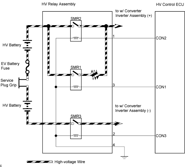
| 1.CHECK HARNESS AND CONNECTOR (HV CONTROL ECU - HV RELAY ASSEMBLY) |
 |
Turn the ignition switch off and remove the service plug grip. (Click here)
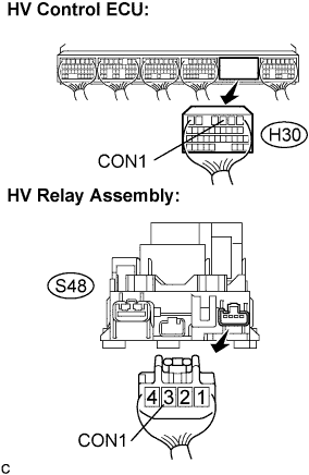
Disconnect the H30 connector from the HV control ECU.
Disconnect the S48 connector from the HV relay assembly.
Measure the voltage according to the value(s) in the table below when the ignition switch is in the ON position.
| Tester Connection | Specified Condition |
| CON1 (H30-3) - Body ground | Below 1 V |
Turn the ignition switch off.
Measure the resistance according to the value(s) in the table below.
| Tester Connection | Specified Condition |
| CON1 (H30-3) - CON1 (S48-3) | Below 1 Ω |
| Tester Connection | Specified Condition |
| CON1 (H30-3) or CON1 (S48-3) - Body ground | 10 kΩ or higher |
|
| ||||
| OK | |
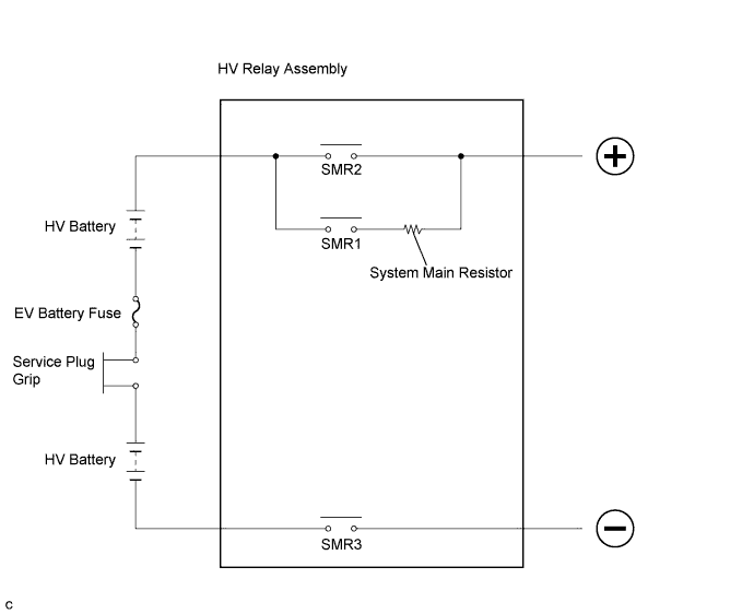
| 2.INSPECT HV RELAY (SMR1) |
 |
Turn the ignition switch off and remove the service plug grip. (Click here)
Remove the HV relay assembly from the vehicle. (Click here)
Measure the resistance according to the value(s) in the table below.
| Tester Connection | Specified Condition |
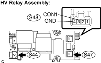
| S47-1 - S44-1 | Below 1 Ω (Apply auxiliary battery voltage between terminals (CON1 (S48-3) and GND (S48-4)) |
Measure the resistance according to the value(s) in the table below.
| Tester Connection | Specified Condition |
| CON1 (S48-3) - GND (S48-4) | 70 to 165 Ω at -30 to 70°C ( -22 to 176°F) |
|
| ||||
| OK | ||
| ||
