DTC    P0AA1-233    Hybrid Battery Positive Contactor Circuit Stuck Closed

for Preparation Click here


DESCRIPTION

  1. Refer to the circuit description for DTC P0AA1-224. (Click here)
  2. This circuit uses the HV control ECU to monitor the system main relays and stops the system if a malfunction is detected in the relays, because it may be impossible to shut off the high-voltage system if any of the relays becomes stuck.

DTC No.
INF Code
DTC Detection Condition
Trouble Area
P0AA1
233
System main relays No.1, No.2, and No.3 on the HV battery positive and negative side stuck closed
HV relay assembly

WIRING DIAGRAM

See the wiring diagram of P0AA1-224. (Click here)

INSPECTION PROCEDURE

CAUTION:
  1. Before inspecting the high-voltage system, take safety precautions to prevent electrical shocks, such as wearing insulated gloves and removing the service plug grip. After removing the service plug grip, put it in your pocket to prevent other technicians from reconnecting it while you are working on the high-voltage system.
  2. After disconnecting the service plug grip, wait for at least 5 minutes before touching any of the high-voltage connectors or terminals.

HINT:
  1. At least 5 minutes is required to discharge the high-voltage capacitor inside the w/ converter inverter assembly.
  2. If P0AA1-233 is output, the vehicle is prevented from starting.

1.READ OUTPUT DTC (HV)
  1. Connect the intelligent tester to the DLC3.

  1. Turn the ignition switch to the ON position.

  1. Select the following menu items: Powertrain / Hybrid Control / DTC.

  1. Read output DTCs. (Click here)

    Result:
    P0A78-523 is output simultaneously.:


YES
GO TO DTC CHART
NO


2.CHECK HV RELAY ASSEMBLY

CAUTION:
Be sure to wear insulated gloves.


    A108057E04
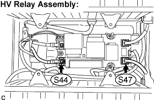
  1. Turn the ignition switch off and remove the service plug grip. (Click here)

    CAUTION:
    Do not reinsert the service plug grip until replacement of the HV relay assembly is completed.

    NOTICE:
    Do not put the vehicle into the READY-on state with the service plug grip removed as this may cause a malfunction.

  1. Measure the resistance according to the value(s) in the table below. (Inspection of SMR1 and SMR2)

    Standard Resistance:
    Tester Connection
    Specified Condition
    S47-1 - S44-1
    10 kΩ or higher

    HINT:
    1. If a system main relay is stuck closed, inspect the HV relay assembly without removing it from the vehicle, in order to keep the relay closed.
    2. If P0AA1-233 is output, the HV relay assembly must be replaced. Measuring resistance can determine that this is either a present or past malfunction.
    3. If the resistance is between 28.5 and 31.5 Ω, it can be determined that the system main relay No.1 is stuck closed.


    A108056E02
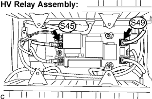
  1. Measure the resistance according to the value(s) in the table below. (Inspection of SMR3)

    Standard Resistance:
    Tester Connection
    Specified Condition
    S49-1 - S45-1
    10 kΩ or higher

    HINT:
    1. If a system main relay is stuck closed, inspect the HV relay assembly without removing it from the vehicle, in order to keep the relay closed.
    2. If P0AA1-233 is output, the HV relay assembly must be replaced. Measuring resistance can determine that this is either a present or past malfunction.


NG
REPLACE HV RELAY ASSEMBLY
OK

REPLACE HV RELAY ASSEMBLY