TERMINALS OF ECM
System information
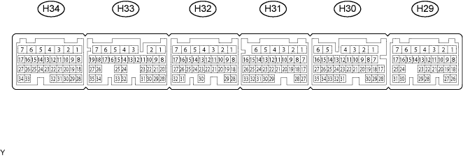

- HINT:
- The standard normal voltage between each pair of ECM terminals is shown in the table below. The appropriate conditions for checking each pair of terminals are also indicated. The result of checks should be compared with the standard normal voltage for that pair of terminals, displayed in the STD Voltage column. The illustration above can be used as a reference to identify the ECM terminal locations.
| Symbols (Terminal No.) |
Wiring Color |
Terminal Description |
Condition |
Specified Condition |
| BATT (H29-1) - E1 (H32-5) |
GR - BR |
Battery (for measuring battery voltage and for ECM memory) |
Always |
9 to 14 V |
| +BM (H31-3) - E1 (H32-5) |
L - BR |
Power source of throttle motor |
Always |
9 to 14 V |
| IGSW (H29-9) - E1 (H32-5) |
G - BR |
Engine switch |
Ignition switch ON |
9 to 14 V |
| +B1 (H31-2) - E1 (H32-5) |
R - BR |
Power source of ECM |
Ignition switch ON |
9 to 14 V |
| +B2 (H31-1) - E1 (H32-5) |
R - BR |
Power source of ECM |
Ignition switch ON |
9 to 14 V |
| OC1+ (H32-16) - OC1- (H32-15) |
G-W - G-R |
Camshaft timing oil control valve (OCV) (Intake side (bank 1)) |
Ignition switch ON |
Pulse generation (see waveform 1) |
| OC2+ (H32-14) - OC2- (H32-13) |
L-R - G-B |
Camshaft timing oil control valve (OCV) (Intake side (bank 2)) |
Ignition switch ON |
Pulse generation (see waveform 1) |
| MREL (H31-12) - E1 (H32-5) |
Y - BR |
EFI MAIN relay |
Ignition switch ON |
9 to 14 V |
| VC (H34-18) - E2 (H34-28) |
Y - BR |
Power source for sensors (specific voltage) |
Ignition switch ON |
4.5 to 5.0 V |
| VG (H34-30) - EVG (H34-29) |
R - G |
Mass air flow meter |
Idling, Shift lever position P or N, A/C switch OFF |
0.5 to 3.0 V |
| THA (H34-20) - E2 (H34-28) |
B-L - BR |
Intake air temperature sensor |
Idling, Intake air temperature 20°C (68°F) |
0.5 to 3.4 V |
| THW (H34-19) - E2 (H34-28) |
G-B - BR |
Engine coolant temperature sensor |
Idling, Engine coolant temperature 80°C (176°F) |
0.2 to 1.0 V |
| VTA (H34-21) - E2 (H34-28) |
W - BR |
Throttle position sensor (for engine control) |
Ignition switch ON, Throttle valve fully closed |
0.5 to 1.2 V |
| VTA (H34-21) - E2 (H34-28) |
W - BR |
Throttle position sensor (for engine control) |
Ignition switch ON, Throttle valve fully open |
3.2 to 4.8 V |
| VTA2 (H34-31) - E2 (H34-28) |
O - BR |
Throttle position sensor (for sensor malfunction detection) |
Ignition switch ON, Accelerator pedal released |
2.1 to 3.1 V |
| VTA2 (H34-31) - E2 (H34-28) |
O - BR |
Throttle position sensor (for sensor malfunction detection) |
Ignition switch ON, Accelerator pedal depressed |
4.5 to 5.0 V |
| VPA1 (H31-25) - EP1 (H31-33) |
O - W-G |
Accelerator pedal position sensor (for engine control) |
Ignition switch ON, Accelerator pedal released |
0.5 to 1.1 V |
| VPA1 (H31-25) - EP1 (H31-33) |
O - W-G |
Accelerator pedal position sensor (for engine control) |
Ignition switch ON, Accelerator pedal depressed |
2.6 to 4.5 V |
| VPA2 (H31-26) - EP2 (H31-32) |
R - Y |
Accelerator pedal position sensor (for sensor malfunctioning detection) |
Ignition switch ON, Accelerator pedal released |
1.2 to 2.0 V |
| VPA2 (H31-26) - EP2 (H31-32) |
R - Y |
Accelerator pedal position sensor (for sensor malfunctioning detection) |
Ignition switch ON, Accelerator pedal depressed |
3.4 to 5.0 V |
| VCP1 (H31-24) - EP2 (H31-32) |
G - Y |
Power source of accelerator pedal position sensor (for VPA) |
Ignition switch ON |
4.5 to 5.0 V |
| VCP2 (H31-31) - EP2 (H31-32) |
BR - Y |
Power source of accelerator pedal position sensor (for VPA2) |
Ignition switch ON |
4.5 to 5.0 V |
| HA1A (H33-4) - E04 (H33-6) HA2A (H33-3) - E05 (H33-5) |
B-W - W-B R-W - BR |
A/F sensor heater |
Idling |
Below 3.0 V |
| HA1A (H33-4) - E04 (H33-6) HA2A (H33-3) - E05 (H33-5) |
B-W - W-B R-W - BR |
A/F sensor heater |
Ignition switch ON |
9 to 14 V |
| A1A+ (H33-22) - E1 (H32-5) |
BR - BR |
A/F sensor |
Ignition switch ON |
3.3 V* |
| A2A+ (H33-23) - E1 (H32-5) |
P - BR |
A/F sensor |
Ignition switch ON |
3.3 V* |
| A1A- (H33-30) - E1 (H32-5) |
Y - BR |
A/F sensor |
Ignition switch ON |
3.0 V* |
| A2A- (H33-31) - E1 (H32-5) |
L - BR |
A/F sensor |
Ignition switch ON |
3.0 V* |
| HT1B (H29-21) - E1 (H32-5) HT2B (H33-33) - E1 (H32-5) |
R - BR W-L - BR |
Heated oxygen sensor heater |
Idling |
Below 3.0 V |
| HT1B (H29-21) - E1 (H32-5) HT2B (H33-33) - E1 (H32-5) |
R - BR W-L - BR |
Heated oxygen sensor heater |
Ignition switch ON |
9 to 14 V |
| OX1B (H29-19) - E2 (H34-28) OX2B (H33-26) - E2 (H34-28) |
B - BR W - BR |
Heated oxygen sensor |
Maintain engine speed at 2,500 rpm for 2 minutes after warming up sensor |
Pulse generation (see waveform 2) |
| #10 (H34-1) - E1 (H32-5) #20 (H34-2) - E1 (H32-5) #30 (H34-3) - E1 (H32-5) #40 (H34-4) - E1 (H32-5) #50 (H34-5) - E1 (H32-5) #60 (H33-7) - E1 (H32-5) |
L - BR Y - BR B - BR W - BR B-W - BR G - BR |
Injector |
Ignition switch ON |
0 to 5 V |
| #10 (H34-1) - E1 (H32-5) #20 (H34-2) - E1 (H32-5) #30 (H34-3) - E1 (H32-5) #40 (H34-4) - E1 (H32-5) #50 (H34-5) - E1 (H32-5) #60 (H33-7) - E1 (H32-5) |
L - BR Y - BR B - BR W - BR B-W - BR G - BR |
Injector |
Idling |
Pulse generation (see waveform 3) |
| KNK1 (H33-29) - EKNK (H33-28) |
B - W |
Knock sensor |
Maintain engine speed at 4,000 after warming up |
Pulse generation (see waveform 4) |
| KNK2 (H33-21) - EKN2 (H33-20) |
R - G |
Knock sensor |
Maintain engine speed at 4,000 after warming up |
Pulse generation (see waveform 4) |
| VV1+ (H32-27) - NE- (H32-24) |
B-W - G |
Variable valve timing (VVT) sensor (Intake side (bank 1)) |
Idling |
Pulse generation (see waveform 5) |
| VV2+ (H32-26) - NE- (H32-24) |
R-L - G |
Variable valve timing (VVT) sensor (Intake side (bank 2)) |
Idling |
Pulse generation (see waveform 5) |
| NE+ (H32-25) - NE- (H32-24) |
R - G |
Crankshaft position sensor |
Idling |
Pulse generation (see waveform 5) |
| IGT1 (H34-8) - E1 (H32-5) IGT2 (H34-9) - E1 (H32-5) IGT3 (H34-10) - E1 (H32-5) IGT4 (H34-11) - E1 (H32-5) IGT5 (H34-12) - E1 (H32-5) IGT6 (H34-13) - E1 (H32-5) |
R-L - BR P - BR Y-B - BR L-Y - BR G-Y - BR L-R - BR |
Ignition coil (ignition signal) |
Idling |
Pulse generation (see waveform 6) |
| IGF1 (H34-24) - E1 (H32-5) |
W-R - BR |
Ignition coil (ignition confirmation signal) |
Ignition switch ON |
4.5 to 5.0 V |
| IGF1 (H34-24) - E1 (H32-5) |
W-R - BR |
Ignition coil (ignition confirmation signal) |
Idling |
Pulse generation (see waveform 6) |
| PRG (H34-17) - E1 (H32-5) |
G - BR |
EVAP VSV |
Ignition switch ON |
9 to 14 V |
| PRG (H34-17) - E1 (H32-5) |
G - BR |
EVAP VSV |
Idling |
Pulse generation (see waveform 7) |
| SPDI (H29-24) - E1 (H32-5) |
LG - BR |
Speed signal from combination meter |
Ignition switch ON, Rotate driving wheel slowly |
Pulse generation (see waveform 8) |
| ST2 (H29-20) - E1 (H32-5) |
Y - BR |
Starter signal |
Ignition switch START |
9 to 14 V |
| STP (H29-31) - E1 (H32-5) |
O - BR |
Stop light switch |
Brake pedal depressed |
7.5 to 14 V |
| STP (H29-31) - E1 (H32-5) |
O - BR |
Stop light switch |
Brake pedal released |
Below 1.5 V |
| ST1- (H29-25) - E1 (H32-5) |
LG - BR |
Stop light switch (opposite to STP terminal) |
Ignition switch ON, Brake pedal depressed |
Below 1.5 V |
| ST1- (H29-25) - E1 (H32-5) |
LG - BR |
Stop light switch (opposite and STP terminal) |
Ignition switch ON, Brake pedal released |
7.5 to 14 V |
| M+ (H32-3) - ME01 (H32-4) |
B - BR |
Throttle actuator |
Idling with warm engine |
Pulse generation (see waveform 9) |
| M- (H32-2) - ME01 (H32-4) |
W - BR |
Throttle actuator |
Idling with warm engine |
Pulse generation (see waveform 10) |
| FC (H31-8) - E1 (H32-5) |
P - BR |
Fuel pump control |
Ignition switch ON |
9 to 14 V |
| FC (H31-8) - E1 (H32-5) |
P - BR |
Fuel pump control |
Idling |
0 to 3 V |
| W (H29-14) - E1 (H32-5) |
BR - BR |
MIL |
Ignition switch ON |
Below 3.0 V |
| W (H29-14) - E1 (H32-5) |
BR - BR |
MIL |
Idling |
0 to 3 V |
| TC (H29-3) - E1 (H32-5) |
BR - BR |
Terminal TC of DLC 3 |
Ignition switch ON |
9 to 14 V |
| CANH (H30-25) - E1 (H32-5) |
B - BR |
CAN communication line |
Ignition switch ON |
Pulse generation (see waveform 11) |
| CANL (H30-33) - E1 (H32-5) |
W - BR |
CAN communication line |
Ignition switch ON |
Pulse generation (see waveform 12) |
- HINT:
- *: The ECM terminal voltage is constant regardless of the output voltage from the sensor.
| WAVEFORM 1 |
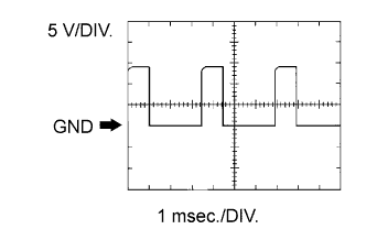 |
| ECM Terminal Name |
Between OC1+ and OC1- or OC2+ and OC2- |
| Tester Range |
5 V/DIV, 1 msec./DIV |
| Condition |
Idling |
- HINT:
- The wavelength becomes shorter as the engine rpm increases.
| WAVEFORM 2 |
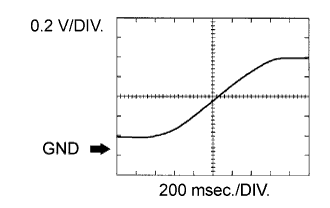 |
| ECM Terminal Name |
Between OX1B and E2 or OX2B and E2 |
| Tester Range |
0.2 V/DIV, 200 msec./DIV |
| Condition |
Engine speed maintained a 2,500 rpm for 2 minutes after warming up engine |
- HINT:
- In DATA LIST, item O2S B1 S2 shows the ECM input values from the heated oxygen sensor.
| WAVEFORM 3 |
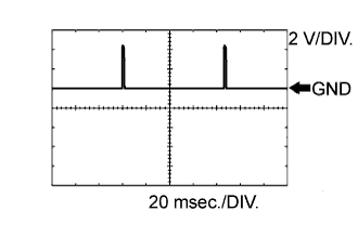 |
| ECM Terminal Name |
Between #10 (to #60) and E1 |
| Tester Range |
2 V/DIV, 20 msec./DIV |
| Condition |
Idling |
- HINT:
- The wavelength becomes shorter as the engine rpm increases.
| WAVEFORM 4 |
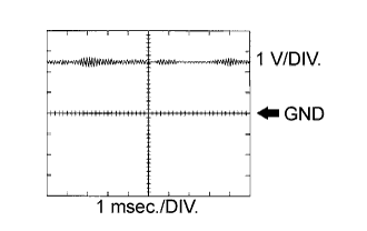 |
| ECM Terminal Name |
Between KNK1 and EKNK1 Between KNK2 and EKNK2 |
| Tester Range |
0.01 to 10 V/DIV, 0.01 to 10 msec./DIV |
| Condition |
Engine speed maintained a 4,000 rpm after warming up engine |
- HINT:
- The wavelength becomes shorter as the engine rpm increases.
- The waveforms and amplitudes displayed differ slightly depending on the vehicle.
- The wavelength becomes shorter as the engine rpm increases.
| WAVEFORM 5 |
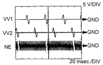 |
| ECM Terminal Name |
Between NE+ and NE- Between VV1+ and NE- or VV2+ and NE- |
| Tester Range |
5 V/DIV, 20 msec./DIV |
| Condition |
Idling |
- HINT:
- The wavelength becomes shorter as the engine rpm increases.
| WAVEFORM 6 |
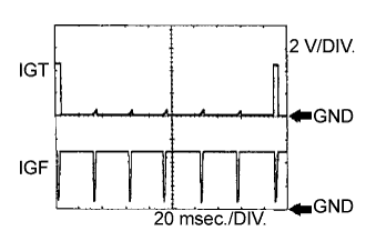 |
| ECM Terminal Name |
Between IGT (1 to 6) and E1 Between IGF1 and E1 |
| Tester Range |
2 V/DIV, 20 msec./DIV |
| Condition |
Idling |
- HINT:
- The wavelength becomes shorter as the engine rpm increases.
| WAVEFORM 7 |
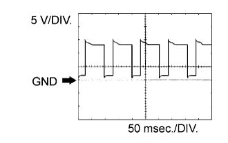 |
| ECM Terminal Name |
Between PRG and E1 |
| Tester Range |
5 V/DIV, 50 msec./DIV |
| Condition |
Idling |
- HINT:
- If the waveform is not similar to the illustration, check the waveform again after idling for 10 minutes or more.
| WAVEFORM 8 |
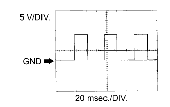 |
| ECM Terminal Name |
Between SPDI and E1 |
| Tester Range |
2 V/DIV, 20 msec./DIV |
| Condition |
Driving at 12 mph (20 km/h) |
- HINT:
- The wavelength becomes shorter as the vehicle speed increases.
| WAVEFORM 9 |
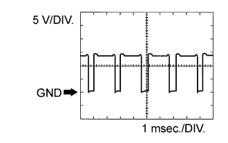 |
| ECM Terminal Name |
Between M+ and ME01 |
| Tester Range |
5 V/DIV, 1 msec./DIV |
| Condition |
Idling with warm engine |
- HINT:
- The duty ratio varies depending on the throttle actuator operation.
| WAVEFORM 10 |
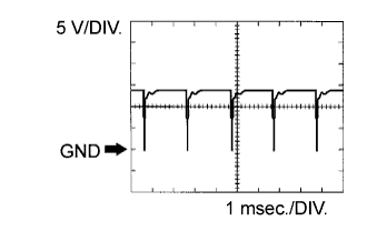 |
| ECM Terminal Name |
Between M- and ME01 |
| Tester Range |
5 V/DIV, 1 msec./DIV |
| Condition |
Idling with warm engine |
- HINT:
- The duty ratio varies depending on the throttle actuator operation.
| WAVEFORM 11 |
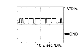 |
| ECM Terminal Name |
Between CANH and E1 |
| Tester Range |
1 V/DIV, 10 μs/DIV |
| Condition |
Stop engine and Ignition switch ON |
- HINT:
- The waveform varies depending on the CAN communication signal.
| WAVEFORM 12 |
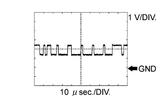 |
| ECM Terminal Name |
Between CANL and E1 |
| Tester Range |
1 V/DIV, 10 μs/DIV |
| Condition |
Stop engine and Ignition switch ON |
- HINT:
- The waveform varies depending on the CAN communication signal.