P0010 Open or short OCV (bank 1) circuit(1 trip detection logic)
Diagnostic trouble codes
DESCRIPTION
The Variable Valve Timing (VVT) system includes the ECM (Included in HV Control ECU), Oil Control Valve (OCV) and VVT controller. The ECM sends a target duty-cycle control signal to the OCV. This control signal regulates the oil pressure supplied to the VVT controller. Camshaft timing control is performed according to engine operating conditions such as intake air volume, throttle valve position and engine coolant temperature. The ECM controls the OCV, based on the signals transmitted by several sensors. The VVT controller regulates the intake camshaft angle using oil pressure through the OCV. As a result, the relative positions of the camshaft and crankshaft are optimized, the engine torque and fuel economy improves, and the exhaust emissions decrease under overall driving conditions. The ECM detects the actual intake valve timing using signals from the camshaft and crankshaft position sensors, and performs feedback control. This is how the target intake valve timing is verified by the ECM.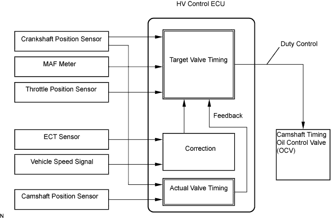

| DTC No. |
DTC Detection Condition |
Trouble Area |
| P0010 |
Open or short OCV (bank 1) circuit (1 trip detection logic) |
|
| P0020 |
Open or short OCV (bank 2) circuit (1 trip detection logic) |
|
WIRING DIAGRAM
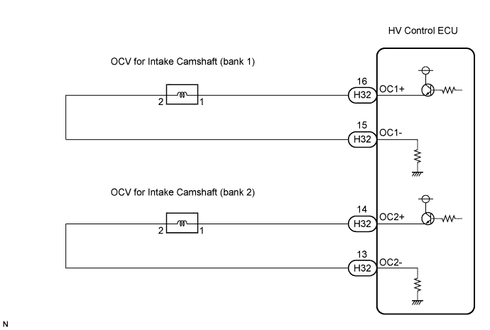
INSPECTION PROCEDURE
- HINT:
- If DTC P0010 is displayed, check the right bank VVT system.
- Bank 1 refers to the bank that includes cylinder No. 1.
- If DTC P0020 is displayed, check the left bank VVT system.
- Bank 2 refers to the bank that does not include cylinder No. 1.
- Read freeze frame data using the intelligent tester. The ECM records vehicle and driving condition information as freeze frame data the moment a DTC is stored. When troubleshooting, freeze frame data can help determine if the vehicle was moving or stationary, if the engine was warmed up or not, if the air-fuel ratio was lean or rich, and other data, from the time the malfunction occurred.
- If DTC P0010 is displayed, check the right bank VVT system.
| 1. PERFORM ACTIVE TEST BY CAMSHAFT TIMING OIL CONTROL VALVE ASSEMBLY (OCV) |

Connect the intelligent tester to the DLC3.
Turn the ignition switch ON and turn the tester ON.
Put the engine in inspection mode (Click here).
Warm up the engine.
On the tester, enter the following menus: Powertrain / Engine / Active Test / Active the VVT System (bank1) or Control the VVT System (bank2).
Check the engine speed while operating the Oil Control Valve (OCV) using the tester.
- OK:
Tester Operation
Specified Condition
OCV OFF
Normal engine speed
OCV ON
Engine idles roughly or stalls (soon after OCV switched from OFF to ON)
|
|
||||

| NG | |
 |
| 2. INSPECT CAMSHAFT TIMING OIL CONTROL VALVE ASSEMBLY (OCV FOR INTAKE CAMSHAFT) |
Disconnect the V7 or V8 OCV connector.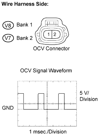
While idling, check the waveform between the terminals of the V7 or V8 OCV connector using an oscilloscope.
- Standard voltage:
Tester Connection
Specified Condition
V8-1 (+) - V8-2 (-)
Correct waveform is as shown
V7-1 (+) - V7-2 (-)
Correct waveform is as shown
Reconnect the OCV connector.
|
|
||||
| NG | |
|
| 3. INSPECT HARNESS AND CONNECTOR (OCV - HV CONTROL ECU) |
Disconnect the V7 or V8 OCV connector.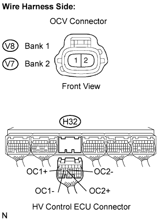
Disconnect the H32 HV Control ECU connector.
Check the resistance between the wire harness side connectors.
- Standard resistance (Check for open):
Tester Connection
Specified Condition
OCV (V8-1) - OC1+ (H32-16)
Below 1 Ω
OCV (V8-2) - OC1- (H32-15)
Below 1 Ω
OCV (V7-1) - OC2+ (H32-14)
Below 1 Ω
OCV (V7-2) - OC2- (H32-13)
Below 1 Ω
- Standard resistance (Check for short):
Tester Connection
Specified Condition
OCV (V8-1) or OC1+ (H32-16) - Body ground
10 kΩ or higher
OCV (V8-2) or OC1- (H32-15) - Body ground
10 kΩ or higher
OCV (V7-1) or OC2+ (H32-14) - Body ground
10 kΩ or higher
OCV (V7-2) or OC2- (H32-13) - Body ground
10 kΩ or higher
Reconnect the OCV connector.
Reconnect the ECM connector.
|
|
||||
| OK | ||
 |
||
| ||