REMOVAL
Removal / installation
| 1. REMOVE ENGINE UNDER COVER NO.1 |

Remove the 6 bolts, 2 screws, 2 clips and engine under cover.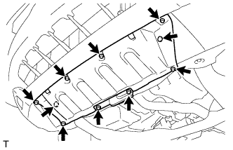

| 2. REMOVE ENGINE UNDER COVER NO.2 |
Remove the 2 bolts and engine under cover No.2.
| 3. DRAIN HYBRID TRANSAXLE FLUID |
Using a socket hexagon wrench 10 mm, remove the filler plug and gasket.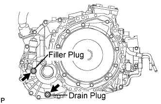
Using a socket hexagon wrench 10 mm, remove the drain plug and gasket.
Using a socket hexagon wrench 10 mm, install the drain plug, and a new gasket.
- Torque:
- 39 N*m{ 398 kgf*cm , 29 ft.*lbf }
| 4. REMOVE FRONT WHEEL |
| 5. REMOVE FRONT AXLE HUB NUT |
Using SST and a hammer, release the staked part of the front axle hub nut.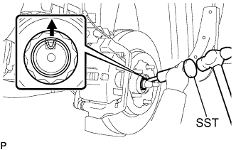
- SST
- 09930-00010
Using a socket wrench (30 mm), remove the axle hub nut.
- NOTICE:
- Loosen the staked part of the nut completely, otherwise the screw of the drive shaft may be damaged.
| 6. SEPARATE SPEED SENSOR FRONT |
Remove the 2 bolts and clip, and separate the sensor wire and hose from the shock absorber.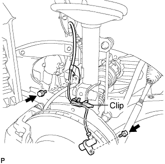
- NOTICE:
- Be careful not to damage the speed sensor.
| 7. SEPARATE FRONT DISC BRAKE CALIPER ASSEMBLY |
Remove the 2 bolts, and separate the brake caliper assembly.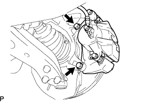
- NOTICE:
- Use a wire or an equivalent to keep the brake caliper from hanging down by the flexible hose.
| 8. REMOVE FRONT DISC |
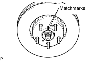 |
- HINT:
- Put matchmarks on the disc and the axle hub.
| 9. SEPARATE FRONT STABILIZER LINK ASSEMBLY |
Support the front suspension lower arm No.1 with a jack using a wooden block to avoid damage.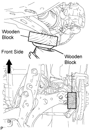
Remove the nut and separate the front stabilizer link assembly from the front shock absorber.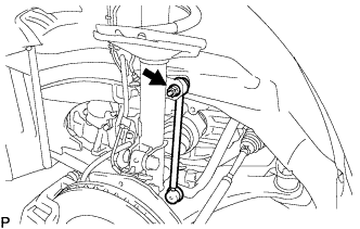
- HINT:
- If the ball joint turns together with the nut, use a hexagon wrench (6 mm) to hold the stud.
| 10. SEPARATE TIE ROD ASSEMBLY |
Remove the cotter pin and nut.
Using SST, separate the tie rod end from the steering knuckle.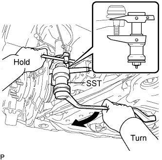
- SST
- 09628-00011
- NOTICE:
- Make sure that the string of the SST is securely tied to the vehicle.
- Be careful not to damage the ball joint dust cover.
- Be careful not to damage the steering knuckle.
- Be careful not to damage the front disc brake dust cover.
- Make sure that the string of the SST is securely tied to the vehicle.
| 11. SEPARATE FRONT SUSPENSION ARM SUB-ASSEMBLY LOWER NO.1 |
Remove the bolt and 2 nuts, and separate the front suspension arm sub-assembly lower No.1 from the lower ball joint.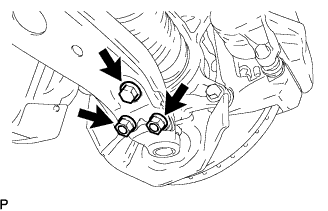
| 12. REMOVE FRONT AXLE ASSEMBLY |
Using a plastic hammer, separate the drive shaft from the axle hub.
Remove the 2 bolts, nuts and steering knuckle.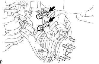
- NOTICE:
- Be careful not to damage the boot and speed sensor rotor.
| 13. REMOVE COWL TOP SILENCER PAD |
Use a screwdriver with its tip taped to disengage the 5 claws and remove the cowl top silencer pad.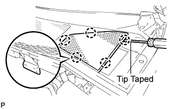
| 14. REMOVE FRONT SHOCK ABSORBER WITH COIL SPRING |
Loosen the lock nut of the front shock absorber with coil spring.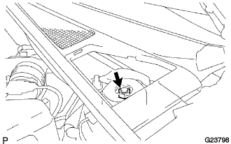
- NOTICE:
- Do not remove the lock nut.
- Only loosen the nut when disassembling the front shock absorber with coil spring.
- Do not remove the lock nut.
Remove the bolt and disconnect the front flexible hose No.2 and front speed sensor wire harness from the front shock absorber with coil spring.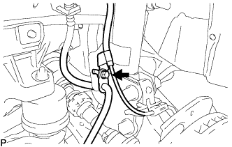
- NOTICE:
- Be sure to remove the front speed sensor from the front shock absorber with coil spring.
Remove the 2 nuts on the lower side of the front shock absorber with coil spring.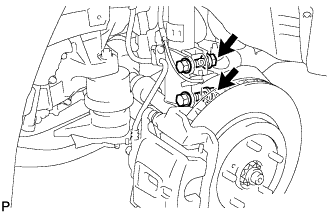
- NOTICE:
- When removing the nuts, keep the bolts from rotating.
- Keep the bolts inserted to secure the front axle assembly.
- When removing the nuts, keep the bolts from rotating.
Remove the 3 nuts on the upper side of the front shock absorber with coil spring.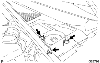
Lower the front axle assembly, and remove the 2 bolts on the lower side of the front shock absorber.
Remove the front shock absorber with coil spring.
- NOTICE:
- Make sure that the front speed sensor is disconnected from the front shock absorber with coil spring.
| 15. REMOVE FRONT DRIVE SHAFT ASSEMBLY LH |
Using SST, remove the front drive shaft assembly LH.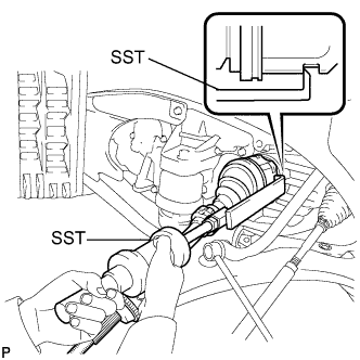
- SST
- 09520-01010
09520-24010 (09520-32040)
- NOTICE:
- Be careful not to damage the transaxle case oil seal and inboard joint boot.
- Be careful not to drop the drive shaft assembly.
- Be careful not to damage the transaxle case oil seal and inboard joint boot.
| 16. REMOVE FRONT DRIVE SHAFT ASSEMBLY RH |
Using pliers, remove the bearing bracket hole snap ring.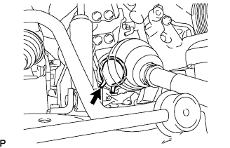
Remove the bolt from the drive shaft bearing bracket.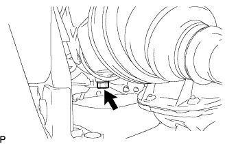
Using SST, remove the front drive shaft assembly RH.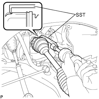
- SST
- 09520-01010
09520-24010 (09520-32040)
- NOTICE:
- Be careful not to damage the transaxle case oil seal and inboard joint boot.
- Be careful not to drop the drive shaft assembly.
- Be careful not to damage the transaxle case oil seal and inboard joint boot.
| 17. REMOVE EXHAUST PIPE ASSEMBLY FRONT |
Remove the 2 nuts, exhaust pipe assembly front, and gasket.
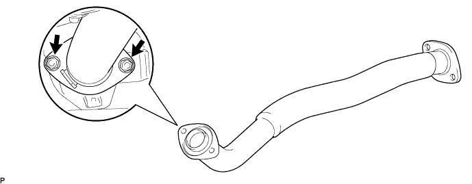
| 18. REMOVE EXHAUST PIPE SUB-ASSEMBLY FRONT NO.3 |
Remove the 2 bolts and 2 nuts, exhaust pipe front No. 3 and the 2 gaskets.
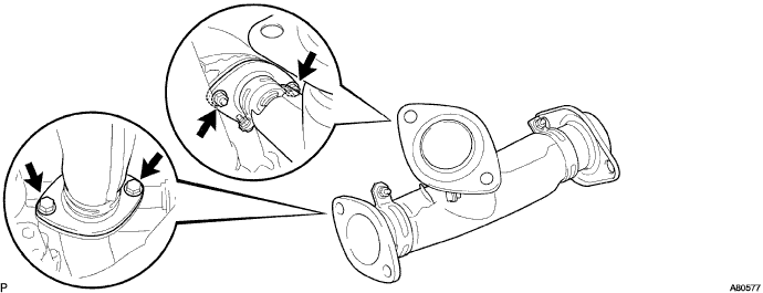
| 19. REMOVE HYBRID TRANSAXLE OIL SEAL |
Remove the oil seal LH side.
Using SST, remove the oil seal.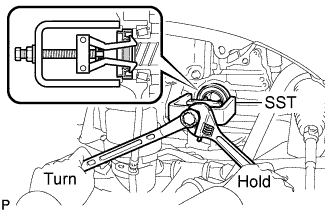
- SST
- 09514-35011
Remove the oil seal RH side.
Using SST, remove the oil seal.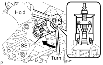
- SST
- 09612-30012