REMOVAL
Removal / installation
| 1. PRECAUTION |

| 2. REMOVE ENGINE UNDER COVER NO.1 |
Remove the 6 bolts, 2 screws, 2 clips and engine under cover.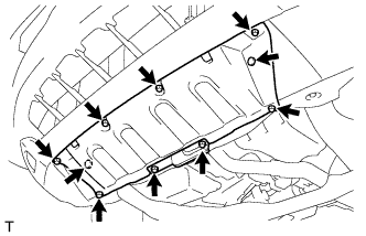

| 3. DRAIN COOLANT (Engine side) |
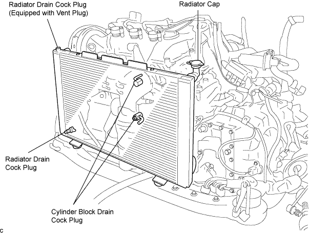
Remove the radiator cap.
- CAUTION:
- To avoid the danger of being burned, do not remove the radiator cap while the engine and radiator are still hot. Thermal expansion will cause hot engine coolant and steam to blow out from the radiator.
Drain the engine coolant by loosening the lower drain plug of the radiator and the cylinder block drain cock plugs.
- HINT:
- Engine coolant inside the radiator is drained from the drain hole located on the bottom of the engine under cover.
Tighten the cylinder block drain cock plugs.
- Torque:
- 13 N*m{ 133 kgf*cm , 9 in.*lbf }
| 4. DRAIN COOLANT (Hybrid side) |
Remove the transaxle side reserve tank.
- NOTICE:
- Do not remove the reserve tank cap when the engine is hot.
Loosen the bleeder plug shown in the illustration and drain the coolant.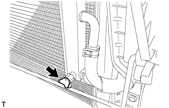
Close the bleeder plug.
Remove the plug and gasket shown in the illustration and drain the coolant.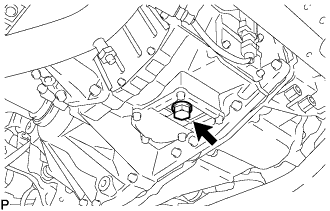
Install the plug with a new gasket.
- Torque:
- 39 N*m{ 398 kgf*cm , 29 ft.*lbf }
| 5. REMOVE W/CONVERTER INVERTER ASSEMBLY |
| 6. REMOVE INVERTER BRACKET NO.1 |
Separate the 3 hose clamps.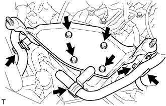
Remove the 4 bolts, harness clamp and inverter bracket.
| 7. REMOVE EMISSION CONTROL VALVE SET |
Disconnect the VSV connector (A).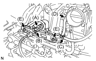
Remove the wire harness clamp (B).
Disconnect the fuel vapor feed hose No. 1 (C).
Disconnect the fuel vapor feed hose No. 2 (D).
Remove the 2 nuts (E), then remove the emission control valve set.
| 8. REMOVE INTAKE AIR SURGE TANK |
Disconnect the throttle motor connector (A).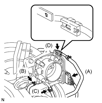
Separate the water by-pass hose No. 2 (B).
Separate the water by-pass hose No. 3 (C).
Separate the fuel vapor feed hose (D).
Disconnect the ventilation hose.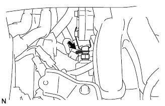
Remove the 2 bolts, then remove the engine hanger No.1 (A).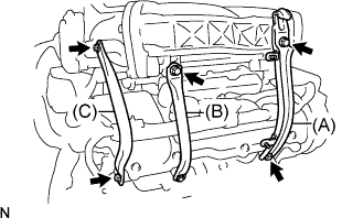
Remove the 2 bolts, then remove the surge tank stay No. 1 (B).
Remove the 2 bolts, then remove the surge tank stay No. 2 (C).
Disconnect the ground cable connector.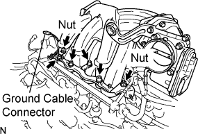
Using a socket hexagon wrench 8 mm, remove the 4 bolts.
Remove the 2 nuts, then remove the emission control valve bracket and the intake air surge tank.
Remove the gasket from the intake air surge tank.
| 9. REMOVE SHIFT LEVER KNOB |
Remove the shift lever knob.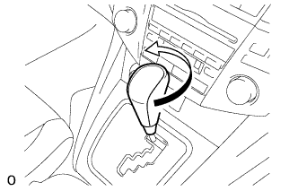
| 10. REMOVE CONSOLE PANEL UPPER FRONT |
Disengage the 4 clips and remove the console panel upper front.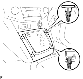
| 11. REMOVE INSTRUMENT PANEL FINISH PANEL LOWER |
Disengage the 2 clips.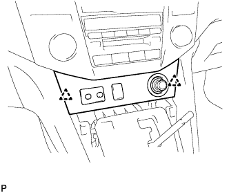
Disconnect the connectors and remove the instrument panel finish panel lower.
| 12. REMOVE FRONT DOOR SCUFF PLATE RH |
- HINT:
- Use the same procedures for the RH side and the LH side.
| 13. REMOVE COWL SIDE TRIM SUB-ASSEMBLY RH |
- HINT:
- Use the same procedures for the RH side and the LH side.
| 14. REMOVE INSTRUMENT PANEL FINISH PANEL SUB-ASSEMBLY LOWER |
Using a screwdriver, open the instrument panel finish panel sub-assembly lower cover.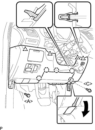
- HINT:
- Tape the screwdriver tip before use.
Remove the bolt <A> and the screw <C>.
Disconnect the hood lock control cable assembly.
Disengage the 5 claws and the 4 clips.
Disconnect the connectors and then remove the instrument panel finish panel sub-assembly lower.
| 15. REMOVE FRONT DOOR SCUFF PLATE LH |
Disengage the 6 claws and 4 clips, and remove the front door scuff plate.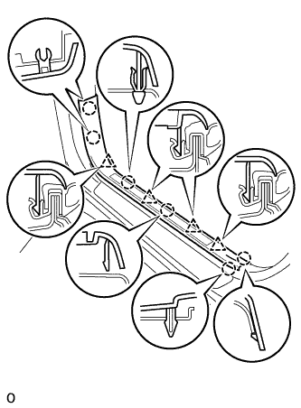
Disconnect the connector. (w/ illumination scuff plate)
| 16. REMOVE COWL SIDE TRIM SUB-ASSEMBLY LH |
Remove the 2 clips and the cowl side trim sub-assembly LH.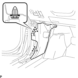
| 17. REMOVE INSTRUMENT PANEL UNDER COVER SUB-ASSEMBLY NO.2 |
Using a screwdriver, push the 3 claws in the direction indicated by the arrow to disengage and remove the guide on the front of the vehicle.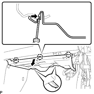
- HINT:
- Tape the screwdriver tip before use.
Disconnect the connectors and remove the instrument panel No.2 under cover sub-assembly.
| 18. REMOVE GLOVE COMPARTMENT DOOR ASSEMBLY |
Remove the 2 bolts <A> and the 2 screws <C>.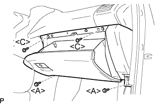
Pull the glove compartment door assembly to the rear to remove it.
Disconnect the connector.
| 19. REMOVE FLOOR CARPET COVER CENTER LH |
Remove the 2 clips from the floor carpet cover center LH.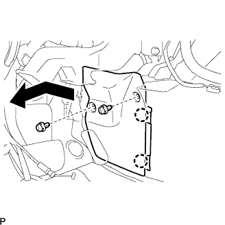
Depress the edge of the floor carpet cover center LH around the claws to disengage the 2 claws below the floor carpet cover center LH.
Slide the floor carpet cover center LH to the front of the vehicle, and disengage the 2 claws from the instrument panel finish panel lower center at the floor carpet center LH.
Remove the floor carpet cover center LH.
| 20. REMOVE FLOOR CARPET COVER CENTER RH |
- HINT:
- Use the same procedures for the RH side and the LH side.
| 21. REMOVE INSTRUMENT PANEL FINISH PANEL LOWER CENTER |
Remove the 7 screws <C>.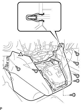
Disengage the 2 clips and remove the instrument panel finish panel lower center.
| 22. REMOVE CONSOLE BOX HOLE COVER |
Slide the front seat assemblies RH and LH forward.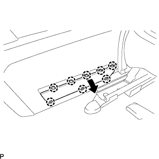
Slide the console box assembly fully to the back end and remove the console box hole cover.
| 23. REMOVE CONSOLE BOX HOLE COVER NO.2 |
- HINT:
- Use the same procedures for the console box No.2 hole cover and the console box hole cover.
| 24. REMOVE CONSOLE BOX ASSEMBLY |
Separate the console box lock control cable assembly from the rear console box.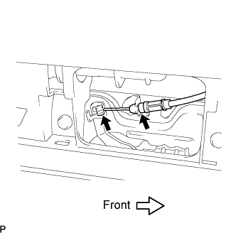
Keeping the rear console box pulled in the rear direction of the vehicle, remove the 6 bolts from the left and right sides.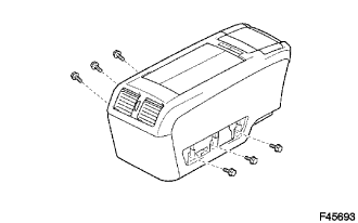
Disconnect each of the clamp and connector.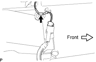
Remove the rear console box.
| 25. REMOVE CONSOLE COVER LOWER |
Remove the 2 screws.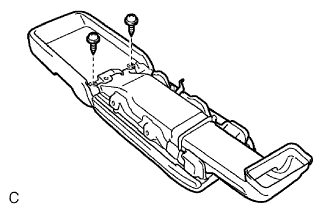
Disconnect the connector and remove the console cover lower.
| 26. SEPARATE TRANSMISSION CONTROL CABLE ASSEMBLY |
In the engine compartment
Remove the nut from the control shaft lever.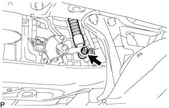
Remove the clip and disconnect the control cable from the control cable bracket.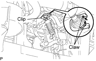
Disconnect the control cable from the control cable bracket No.2.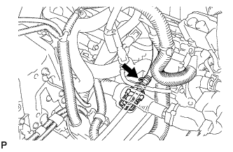
In the cabin
Using a screwdriver, disconnect the cable end from the shift lever assembly.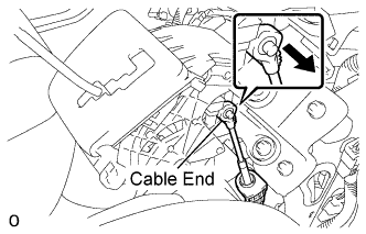
Pull out the stopper cap of the transmission control cable assembly.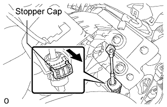
Turn the socket of the transmission control cable counterclockwise and remove the stopper cap.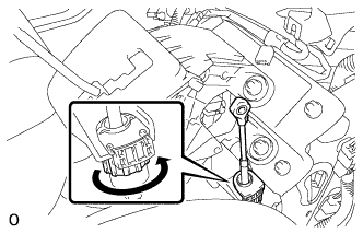
- NOTICE:
- Do not push in the stopper cap.
| 27. REMOVE SHIFT LEVER |
Disconnect the pattern select switch connector, the shift lock control computer connector and the indicator light wire connector.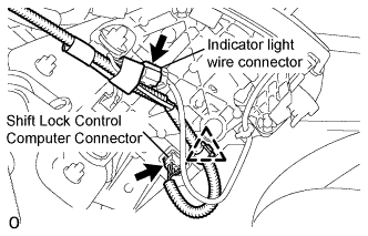
Remove the 4 nuts and disconnect the shift lever assembly from the vehicle.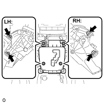
| 28. REMOVE CONSOLE BOX DUCT NO.1 |
| 29. REMOVE AIR DUCT REAR NO.1 |
Turn back the floor carpet.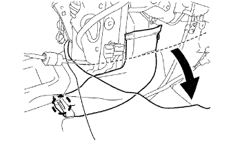
- HINT:
- Turn back the floor carpet so that the air duct rear No.1 can be removed.
Release the claw and remove the air duct rear No.1.
| 30. REMOVE AIR DUCT REAR NO.2 |
Turn back the floor carpet.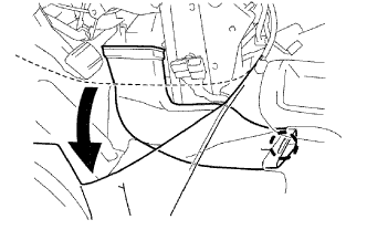
- HINT:
- Turn back the floor carpet so that the air duct rear No.2 can be removed.
Release the claw and remove the air duct rear No.2.
| 31. REMOVE AIR BAG SENSOR ASSEMBLY CENTER |
Disconnect the 3 connectors from the center airbag sensor assembly.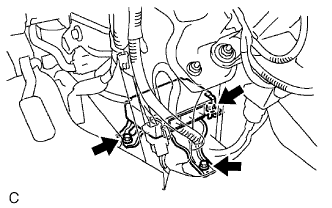
Remove the 3 bolts and the center airbag sensor assembly.
| 32. REMOVE TRANSMISSION CONTROL CABLE ASSEMBLY |
Remove the 3 bolts.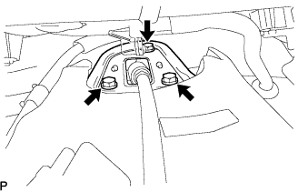
Pull out the control cable from the body.