REASSEMBLY
Removal / installation
| 1. INSTALL FRONT DRIVE SHAFT BEARING |

Using SST and a press, install a new front drive shaft bearing.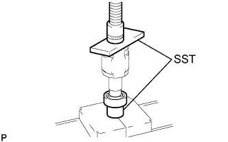

- SST
- 09726-40010
09527-10011
- NOTICE:
- The bearing should be completely installed.
| 2. INSTALL FRONT DRIVE SHAFT RH HOLE SNAP RING |
Using a snap ring expander, install a new front drive shaft RH hole snap ring.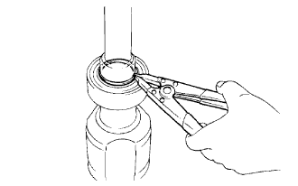
| 3. INSTALL FRONT DRIVE SHAFT DUST COVER |
Using SST and a press, install a new drive shaft dust cover until the distance from the tip of the center drive shaft to the drive shaft dust cover meets the specification, as shown in the illustration.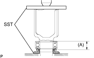
- SST
- 09726-40010
09527-10011
- Distance (A):
- 26.8 to 27.4 mm (1.0551 to 1.0787 in.)
| 4. INSTALL FRONT DRIVE SHAFT DUST COVER LH |
Using SST and a press, install a new drive shaft dust cover LH.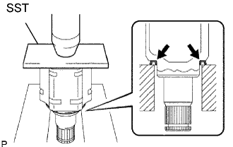
- SST
- 09527-10011
- NOTICE:
- The dust cover should be completely installed.
- Be careful not to damage the dust cover.
- The dust cover should be completely installed.
| 5. INSTALL FRONT DRIVE SHAFT DUST COVER RH |
Using SST and a press, install a new drive shaft dust cover RH until the distance from the tip of the center drive shaft to the drive shaft dust cover RH meets the specification, as shown in the illustration.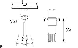
- SST
- 09527-10011
- Distance (A):
- 109.5 mm (4.311 in.)
| 6. INSTALL FRONT DRIVE SHAFT LH HOLE SNAP RING |
Install a new hole snap ring to the inboard joint shaft assembly.
| 7. INSTALL OUTBOARD JOINT BOOT |
- HINT:
- Before installing the boots, wrap the spline of the drive shaft with vinyl tape to prevent the boots from being damaged.
Install new parts to the outboard joint shaft assembly in the following order: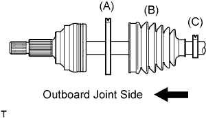
Outboard joint boot No.2 clamp (A)
Outboard joint boot (B)
Outboard joint boot clamp (C)
Pack the outboard joint shaft and boot with grease.
- Grease capacity:
- 205 to 225 g (7.2 to 7.9 oz.)
| 8. INSTALL OUTBOARD JOINT BOOT NO.2 CLAMP |
Hold the outboard joint shaft assembly between aluminium plates in a vise.
- NOTICE:
- Do not overtighten the vise.
Install the outboard joint boot No.2 clamp onto the boot.
Place SST onto the outboard joint boot No.2 clamp.
- SST
- 09521-24010
Tighten the SST so that the outboard joint boot No.2 clamp is pinched.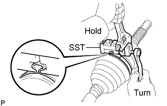
- SST
- 09521-24010
- NOTICE:
- Do not overtighten the SST.
Using SST, measure the clearance of the outboard joint boot No.2 clamp.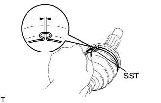
- SST
- 09240-00020
- Clearance:
- 0.8 mm (0.031 in.) or less
- NOTICE:
- When the measured value is greater than the specified value, retighten the clamp.
| 9. INSTALL OUTBOARD JOINT BOOT CLAMP |
Install the outboard joint boot clamp and using the same procedure as for the outboard joint boot No.2 clamp.
| 10. INSTALL FRONT DRIVE SHAFT DAMPER |
Install the drive shaft damper to the drive shaft.
Make sure that the damper is aligned with the shaft groove to ensure secure tightening of the clamp.
Set the distance as specified below.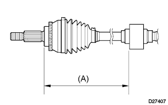
- Distance (A):
- 225.5 to 229.5 mm (8.8779 to 9.0354 in.)
| 11. INSTALL FRONT DRIVE SHAFT DAMPER CLAMP |
Hold the outboard joint shaft assembly between aluminium plates in a vise.
- NOTICE:
- Do not overtighten the vise.
Using a screwdriver, install the drive shaft damper clamp as shown in the illustration.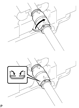
| 12. INSTALL INBOARD JOINT SHAFT ASSEMBLY |
Install a new inboard joint boot to the outboard joint shaft assembly.
Hold the outboard joint shaft assembly between aluminium plates in a vise.
- NOTICE:
- Do not overtighten the vise.
Place the beveled side of the tripod axial spline toward the outboard joint shaft.
Align the matchmarks.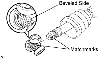
Using a brass bar and a hammer, tap in the tripod to the outboard joint shaft.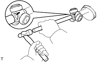
- NOTICE:
- Do not tap the roller.
- Be sure to install the tripod in the correct direction.
- Do not tap the roller.
Using a snap ring expander, install a new front inner shaft snap ring.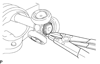
Pack the inboard joint shaft and boot with grease.
- Grease capacity:
- 155 to 175 g (5.5 to 6.2 oz.)
Align the matchmarks and install the inboard joint assembly to the outboard joint shaft assembly.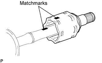
| 13. INSTALL INBOARD JOINT BOOT |
Install the inboard joint boot to the inboard joint shaft assembly.
| 14. INSTALL INBOARD JOINT BOOT NO.2 CLAMP |
Hold the outboard joint shaft assembly between aluminium plates in a vise.
- NOTICE:
- Do not overtighten the vise.
Using a screwdriver, install the inboard joint boot No.2 clamp as shown in the illustration.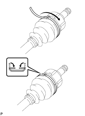
| 15. INSTALL INBOARD JOINT BOOT CLAMP |
Install the inboard joint boot clamp and using the same procedure as for the inboard joint boot No.2 clamp.
| 16. INSPECT FRONT DRIVE SHAFT ASSEMBLY |
Check that there is no excessive play in the outboard joint.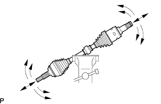
Check that the inboard joint slides smoothly in the thrust direction.
Check that there is no excessive play in the radial directions of the inboard joint.
Check that the boots are not punctured or torn open.