REMOVAL
Removal / installation
| 1. REMOVE FRONT WHEEL |
| 2. REMOVE FRONT AXLE HUB NUT |

Using SST and a hammer, release the staked part of the front axle hub nut.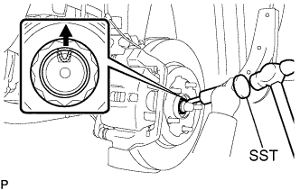

- SST
- 09930-00010
Using a socket wrench (30 mm), remove the axle hub nut.
- NOTICE:
- Loosen the staked part of the nut completely, otherwise the screw of the drive shaft may be damaged.
| 3. SEPARATE FRONT SPEED SENSOR |
Remove the 2 bolts and clip, and separate the sensor wire and hose from the shock absorber.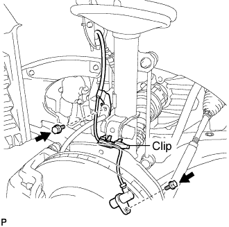
- NOTICE:
- Be careful not to damage the speed sensor.
| 4. SEPARATE FRONT DISC BRAKE CALIPER ASSEMBLY |
Remove the 2 bolts, and separate the brake caliper assembly.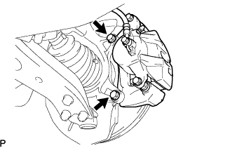
- NOTICE:
- Use a wire or an equivalent to keep the brake caliper from hanging down by the flexible hose.
| 5. REMOVE FRONT DISC |
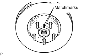 |
- HINT:
- Put matchmarks on the disc and the axle hub.
| 6. SEPARATE TIE ROD ASSEMBLY |
Remove the cotter pin and nut.
Using SST, separate the tie rod end from the steering knuckle.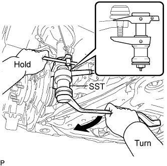
- SST
- 09628-00011
- NOTICE:
- Make sure that the string of the SST is securely tied to the vehicle.
- Be careful not to damage the ball joint dust cover.
- Be careful not to damage the steering knuckle.
- Be careful not to damage the front disc brake dust cover.
- Make sure that the string of the SST is securely tied to the vehicle.
| 7. SEPARATE FRONT SUSPENSION ARM SUB-ASSEMBLY LOWER NO.1 |
Remove the bolt and 2 nuts, and separate the front suspension arm sub-assembly lower No.1 from the lower ball joint.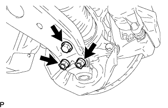
| 8. REMOVE FRONT AXLE ASSEMBLY |
Using a plastic hammer, separate the drive shaft from the axle hub.
Remove the 2 bolts, nuts and steering knuckle.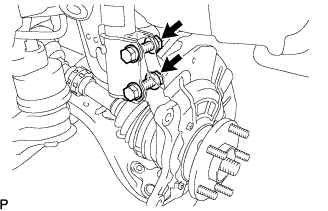
- NOTICE:
- Be careful not to damage the boot and speed sensor rotor.
| 9. REMOVE FRONT WHEEL BEARING DUST DEFLECTOR NO.1 |
Using a screwdriver with its tip wrapped with vinyl tape, remove the bearing dust deflector No.1.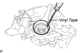
- NOTICE:
- Be careful not to damage the steering knuckle.
| 10. REMOVE FRONT AXLE HUB HOLE SNAP RING |
Using snap ring pliers, remove the front axle hub hole snap ring.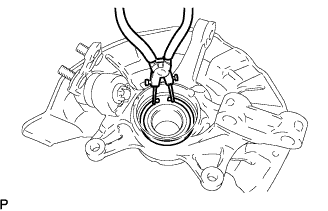
| 11. REMOVE FRONT AXLE HUB SUB-ASSEMBLY |
Hold the front axle assembly between aluminium plates in a vise.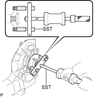
- NOTICE:
- Do not overtighten the vise.
Using SST, remove the front axle hub sub-assembly.
- SST
- 09520-00031
Using SST and a press, remove the bearing inner race (outside) from the front axle hub sub-assembly.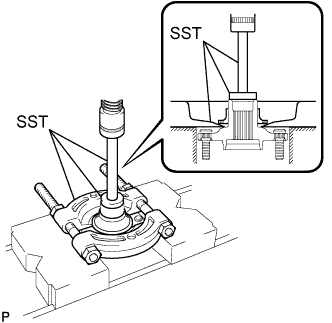
- SST
- 09950-60010
(09951-00430)
09950-70010 (09951-07100)
09555-55010
- NOTICE:
- Be careful not to drop the front axle hub sub-assembly.
| 12. REMOVE FRONT DISC BRAKE DUST COVER |
Remove the 4 bolts and disc brake dust cover from steering knuckle.
| 13. REMOVE FRONT LOWER BALL JOINT ASSEMBLY |
Secure the steering knuckle in a vise using aluminum plates.
Remove the cotter pin and nut.
Using SST, remove the front lower ball joint.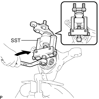
- SST
- 09628-62011
- NOTICE:
- Do not damage the dust cover of the ball joint.
- Do not damage the steering knuckle.
- Do not damage the dust cover of the ball joint.
| 14. REMOVE FRONT AXLE HUB BEARING |
Place the bearing inner race (outside) on the front axle hub bearing.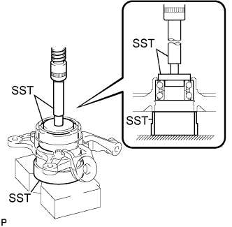
Using SST and a press, press the front axle hub bearing until it contacts the SST.
- SST
- 09527-17011
09950-60010 (09951-00600, 09951-00400, 09952-06010)
09950-70010 (09951-07100)
Using SST to make the steering knuckle horizontal, fix it to the V-block, as shown in the illustration.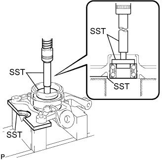
Using SST and a press, remove a front axle hub bearing to the steering knuckle.
- SST
- 09950-60010
(09951-00600, 09951-00400, 09952-06010)
09950-70010 (09951-07100)
09527-20011