P0560 Open in ECM back-up power source circuit(1 trip detection logic)
Diagnostic trouble codes
DESCRIPTION
The battery supplies electricity to the ECM (Included in HV Control ECU) even when the engine switch is in the off position. This power allows the ECM to store data such as DTC history, freeze frame data and fuel trim values. If the battery voltage falls below a minimum level, these memories are cleared and the ECM determines that there is a malfunction in the power supply circuit. When the engine is next started, the ECM will illuminates the MIL and sets the DTC.| DTC No. |
DTC Detection Condition |
Trouble Area |
| P0560 |
Open in ECM back-up power source circuit (1 trip detection logic) |
|
- HINT:
- If DTC P0560 is set, the ECM does not store other DTCs.
WIRING DIAGRAM
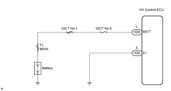

INSPECTION PROCEDURE
- HINT:
- Read freeze frame data using the intelligent tester. The ECM records vehicle and driving condition information as freeze frame data the moment a DTC is stored. When troubleshooting, freeze frame data can help determine if the vehicle was running or stopped, if the engine was warmed up or not, if the air-fuel ratio was lean or rich, and other data from the time the malfunction occurred.
| 1. CHECK FUSE (IGCT NO.5 FUSE) |

Remove the IGCT No.5 fuse from the fusible link block.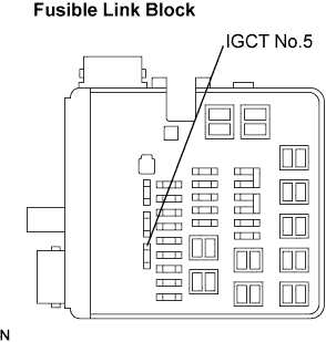
Measure the resistance.
- Standard resistance:
- Below 1 Ω
Reinstall the IGCT No.5 fuse.
|
|
||||

| OK | |
 |
| 2. INSPECT HV CONTROL ECU (BATT VOLTAGE) |
Measure the voltage between the terminals of the H29 and H32 HV Control ECU connectors.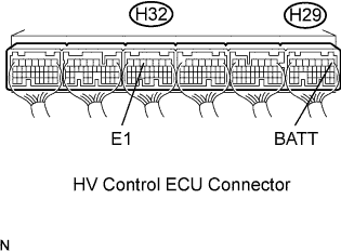
- Standard voltage:
Tester Connection
Specified Condition
BATT (H29-1) - E1 (H32-5)
9 to 14 V
|
|
||||

| OK | ||
 |
||
| ||
| 3. CHECK HARNESS AND CONNECTOR (HV CONTROL ECU - IGCT NO.5 FUSE, IGCT NO.5 FUSE - BATTERY) |
Check the harness and the connector between the IGCT No.5 fuse and HV Control ECU.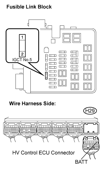
Remove the IGCT No.5 fuse from the fusible link block.
Disconnect the H29 HV Control ECU connector.
Measure the resistance.
- Standard resistance (Check for open):
Tester Connection
Specified Condition
IGCT No.5 fuse (2) - BATT (H29-1)
Below 1 Ω
- Standard resistance (Check for short):
Tester Connection
Specified Condition
IGCT No.5 fuse (2) or BATT (H29-1) - Body ground
10 kΩ or higher
Reconnect the HV Control ECU connector.
Reinstall the IGCT No.5 fuse.
Check the harness and the connector between the IGCT No.5 fuse and battery.
Remove the IGCT No.5 fuse from the fusible link block.
Disconnect the positive battery terminal.
Measure the resistance.
- Standard resistance (Check for open):
Tester Connection
Specified Condition
Battery positive terminal - IGCT No.5 fuse (1)
Below 1 Ω
- Standard resistance (Check for short):
Tester Connection
Specified Condition
Battery positive terminal or IGCT No.5 fuse (1) - Body ground
10 kΩ or higher
Reconnect the positive battery terminal.
Reinstall the IGCT No.5 fuse.
|
|
||||
| OK | |
|
| 4. INSPECT BATTERY |
Check that the battery is not depleted.
|
|
||||
| OK | ||
|
||
| ||