REMOVAL
Removal / installation
| 1. PRECAUTION |

- CAUTION:
- Be sure to read "PRECAUTION" thoroughly before servicing (Click here).
| 2. DISCONNECT CABLE FROM NEGATIVE BATTERY TERMINAL |
- CAUTION:
- Wait for 90 seconds after disconnecting the cable to prevent the airbag working
| 3. PLACE FRONT WHEELS FACING STRAIGHT AHEAD |
| 4. REMOVE STEERING WHEEL NO.3 COVER LOWER |
Using a screwdriver, remove the steering wheel No.3 cover lower.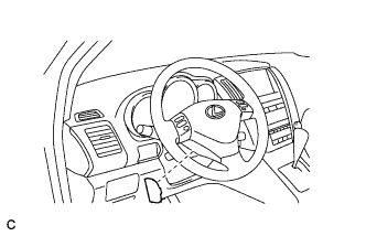

- HINT:
- Tape up the screwdriver tip before use.
| 5. REMOVE STEERING WHEEL NO.2 COVER LOWER |
Using a screwdriver, remove the steering wheel No.2 cover lower.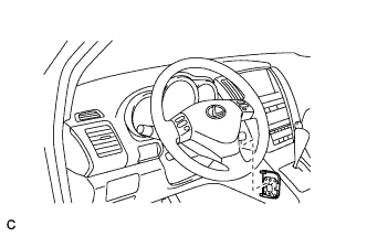
- HINT:
- Tape up the screwdriver tip before use.
| 6. REMOVE STEERING PAD |
Using a "torx" socket wrench (T30), loosen the 2 "torx" screws until the groove along the screw circumference catches on the screw case.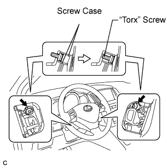
Pull out the steering pad from the steering wheel assembly and support the steering pad with one hand as shown in the illustration.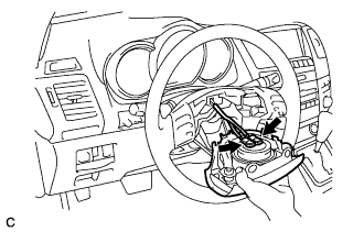
- NOTICE:
- When removing the steering pad, do not pull the airbag wire harness.
Disconnect the horn connector.
Disconnect the 2 connectors from the steering pad.
- NOTICE:
- When handling the airbag connector, take care not to damage the airbag wire harness.
Remove the steering pad.
| 7. REMOVE STEERING WHEEL ASSEMBLY (for Manual Tilt) |
Remove the steering wheel assembly set nut.
Put matchmarks on the steering wheel assembly and main shaft assembly.
Using SST, remove the steering wheel assembly.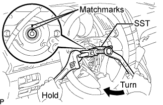
- SST
- 09950-50013
(09951-05010, 09952-05010, 09953-05020, 09954-05021)
| 8. REMOVE STEERING WHEEL ASSEMBLY (for Power Tilt and Power Telescopic) |
Remove the steering wheel assembly set nut.
Put matchmarks on the steering wheel assembly and main shaft assembly.
Using SST, remove the steering wheel assembly.
- SST
- 09950-50013
(09951-05010, 09952-05010, 09953-05020, 09954-05031)
| 9. REMOVE STEERING COLUMN COVER (for Manual Tilt) |
Remove the steering column cover lower No.2.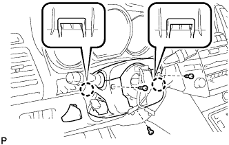
Remove the 3 screws.
Disengage the 2 claws and remove the steering column cover lower.
Disengage the claw and remove the steering column cover upper.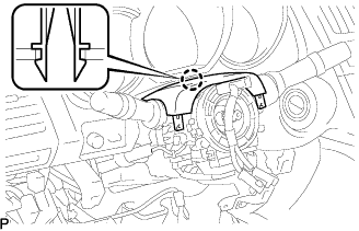
| 10. REMOVE STEERING COLUMN COVER (for Power Tilt and Power Telescopic) |
Remove the 3 screws.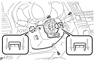
Disengage the 2 claws and remove the steering column cover lower.
- NOTICE:
- Do not damage the tilt and telescopic switch.
Disengage the claw and remove the steering column cover upper.
| 11. REMOVE SPIRAL CABLE |
Disconnect the connectors from the spiral cable.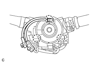
- NOTICE:
- When handling the airbag connector, take care not to damage the airbag wire harness.
Disengage the 3 claws and remove the spiral cable.
| 12. REMOVE STEERING ANGLE SENSOR |
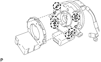
Disengage the 6 claws and remove the steering angle sensor from the spiral cable sub-assembly.