REMOVAL
Removal / installation
| 1. PRECAUTION |

| 2. DISCONNECT CABLE FROM NEGATIVE BATTERY TERMINAL |
| 3. REMOVE SERVICE PLUG GRIP |
- CAUTION:
- Remove the service plug to interrupt a high voltage circuit at the time of the check.
- Keep the removed service plug in your pocket to prevent other technicians from reconnecting it while you are servicing the vehicle.
- All the high voltage wiring connectors are colored in orange.
- Remove the service plug to interrupt a high voltage circuit at the time of the check.
Remove the 2 clips, then open the battery service hole cover.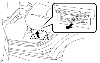

Wear insulation glove, and remove the service plug grip, after sliding up the lever of the service plug grip.
- CAUTION:
- Keep the removed service plug in your pocket to prevent other technicians from reconnecting it while you are servicing the vehicle.
- After removing the service plug grip, do not touch the high voltage connectors and terminals for 5 minutes.
- Keep the removed service plug in your pocket to prevent other technicians from reconnecting it while you are servicing the vehicle.
- NOTICE:
- After removing the service plug grip, do not operate the ignition switch as it may damage the hybrid vehicle control ECU.
| 4. REMOVE DECK BOARD SUB-ASSEMBLY |
Disengage the 5 clips and turn up the front side of the deck board.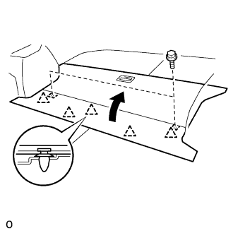
Remove the 2 bolts and deck board sub-assembly.
| 5. REMOVE DECK FLOOR BOX REAR |
Using a clip remover, remove the 2 clips and deck floor box rear.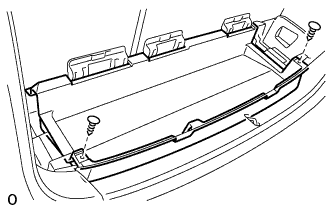
| 6. REMOVE REAR FLOOR FINISH PLATE |
Using a clip remover, remove the 2 clips.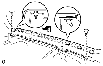
Disengage the 2 claws and 6 clips, and remove the rear floor finish plate.
| 7. REMOVE DECK FLOOR BOX FRONT |
Using a clip remover, remove the 2 clips and deck floor box front.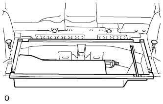
| 8. REMOVE DECK BOARD SUB-ASSEMBLY NO.2 |
Remove the 4 blots, 2 nuts and deck No.2 board sub-assembly.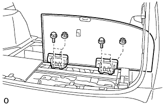
| 9. REMOVE DECK BOARD SUB-ASSEMBLY NO.3 |
Remove the 2 bolts, 2 nuts and deck No.3 board sub-assembly.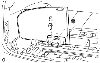
| 10. REMOVE DECK SIDE TRIM BOX RH |
| 11. REMOVE DECK SIDE TRIM BOX LH |
Remove the clip (A).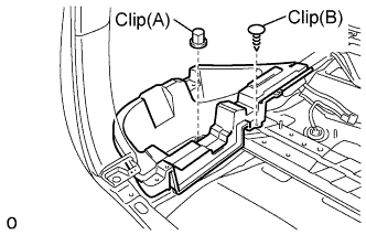
Using a clip remover, remove the clip (B) and deck side trim box.
| 12. REMOVE DECK BOARD CHECK NO.1 |
Remove the 4 nuts and deck board check No.1.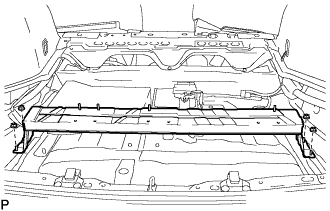
| 13. REMOVE POWER STEERING CONVERTER COVER |
Separate the wire harness clamp from the power steering converter cover.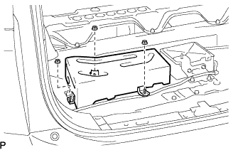
Remove the 3 nuts and the power steering converter cover.
| 14. SEPARATE POWER STEERING CONVERTER ASSEMBLY |
Remove the nut, and disconnect the No.3 wire frame from the power steering converter assembly.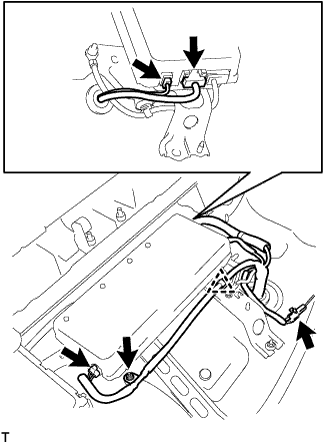
Remove the 4 connectors and clamp, and disconnect the No.3 wire frame from the power steering converter assembly.
| 15. REMOVE REAR SEAT TRACK BRACKET COVER |
Move the rear seat assembly LH to the rearmost position by operating the rear seat track adjusting handle.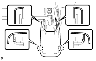
Using a screwdriver, disengage the 4 claws.
- HINT:
- Tape the screwdriver tip before use.
Pull the 2 rear seat track bracket covers toward the rear of the vehicle and remove them.
| 16. REMOVE REAR SEAT ASSEMBLY LH |
Using a clip remover, remove the 3 clips.
Remove the bolt and disconnect the floor anchor side of the fold seat stopper band assembly No.2.
Move the rear seat assembly LH to the rearmost position by operating the rear seat track adjusting handle.
Remove the 2 bolts on the front side.
Move the rear seat assembly LH fully forward by operating the rear seat track adjusting handle.
Remove the 3 bolts on the rear side.
Move the rear seat assembly LH to the center position and adjust the seatback to the vertical position.
Remove the rear seat assembly LH.
| 17. REMOVE REAR SEAT TRACK BRACKET COVER |
Move the rear seat assembly RH to the rearmost position by operating the rear seat track adjusting handle.
Using a screwdriver, disengage the 4 claws.
- HINT:
- Tape the screwdriver tip before use.
Pull the 2 rear seat track bracket covers toward the rear of the vehicle and remove them.
| 18. REMOVE REAR SEAT ASSEMBLY RH |
Using a clip remover, remove the 5 clips.
Remove the bolt and disconnect the floor anchor side of the fold seat stopper band assembly No.1.
Move the rear seat assembly RH to the rearmost position by operating the rear seat track adjusting handle.
Remove the 2 bolts on the front side.
Move the rear seat assembly RH fully forward by operating the rear seat track adjusting handle.
Remove the 3 bolts on the rear side.
Move the rear seat assembly RH to the center position and adjust the seatback to the vertical position.
Remove the rear seat assembly RH.
| 19. REMOVE AIR INTAKE COVER |
Remove the air intake cover LH.
Release the claw by using the screwdriver with the tip taped, and remove the 2 hole covers.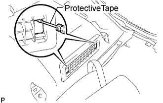
Remove the 2 screws, then release the 2 claws and remove air intake cover LH.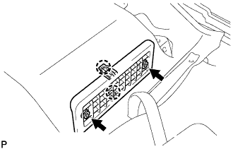
Remove the air intake cover RH.
Release the claw by using the screwdriver with the tip taped, and remove the 2 hole covers.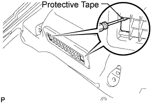
Remove the 2 screws, then release the 2 claws and remove air intake cover RH.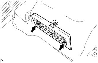
| 20. REMOVE AIR INTAKE COVER CENTER |
Release the claw by using the screwdriver with the tip taped, and remove the 2 hole covers.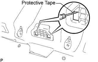
Remove the 2 screws, then release the 2 claws and remove air intake cover center.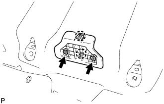
| 21. SEPARATE FLOOR CARPET ASSEMBLY FRONT |
Turn back the front floor carpet assembly.
| 22. REMOVE HYBRID VEHICLE BATTERY SERVICE HOLE COVER |
Using the service plug grip, remove the battery cover lock striker.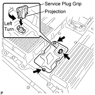
- HINT:
- Insert the projection part of the service plug grip, and turn the button of the battery cover lock striker counterclockwise, and release the lock.
Remove the 2 bolts and battery service hole cover.
| 23. DISCONNECT HYBRID VEHICLE RELAY ASSEMBLY |
- CAUTION:
- Wear insulating gloves.
- NOTICE:
- Insulate the removed terminals with insulating tape.
Remove the bolt, then disconnect the frame wire No.3.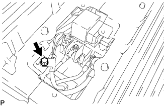
Disconnect the No.3 wire frame connector to the hybrid vehicle relay assembly.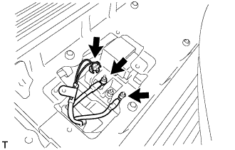
Remove the 2 nuts, and disconnect the hybrid vehicle relay assembly.
| 24. REMOVE ENGINE ROOM SIDE LH COVER |
Using a clip remover, remove the engine room side cover.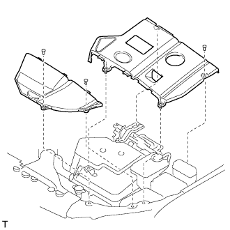
| 25. REMOVE FRONT WIPER ARM AND BLADE ASSEMBLY RH |
Remove the 2 nuts and the front wiper arm and blade assembly RH.
| 26. REMOVE FRONT WIPER ARM AND BLADE ASSEMBLY LH |
Remove the nut and the front wiper arm and blade assembly LH.
| 27. REMOVE COWL TOP VENTILATOR LOUVER SUB-ASSEMBLY |
Remove the 2 clips.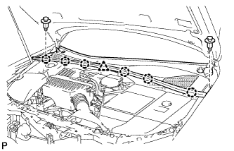
Disengage the 6 claws and the clamp, and remove the cowl top ventilator louver sub-assembly.
| 28. REMOVE WINDSHIELD WIPER LINK ASSEMBLY |
Disconnect the connector.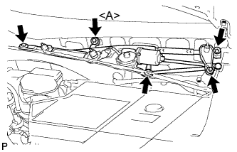
Remove the 5 bolts and the windshield wiper motor and link assembly.
- HINT:
- Bolt <A> cannot be removed because it is integrated into windshield wiper link assembly.
| 29. REMOVE COWL TOP PANEL SUB-ASSEMBLY OUTER |
Separate the wire harness clamp and grommet (A).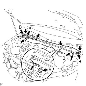
Remove the 4 shock absorber nuts (B).
Remove the 4 bolts, 2 nuts and cowl top panel sub-assembly.
Install the 4 shock absorber nuts.
- Torque:
- 80 N*m{ 815 kgf*cm , 59 ft.*lbf }
| 30. REMOVE COOL AIR INTAKE DUCT SEAL |
Remove the 4 clips and cool air intake duct seal.
| 31. REMOVE AIR CLEANER CAP W/INLET |
Remove the 2 bolts, 4 clamps and air cleaner cap w/ inlet.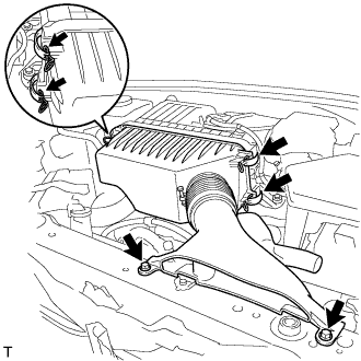
Remove the air cleaner filter element from the air cleaner case.
| 32. REMOVE AIR CLEANER W/RESONATOR |
Separate the ventilation hose No.2.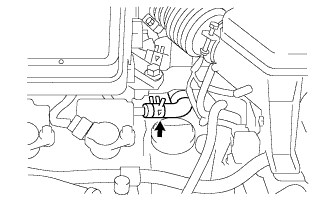
Disconnect the MAF meter connector.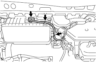
Disconnect the 2 wire harness clamps from the air cleaner.
Remove the 5 bolts from the air cleaner case w/ resonator.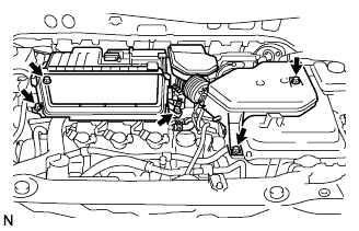
Remove the hose clamp, and separate the air cleaner hose No.1.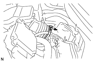
Remove the air cleaner case w/ resonator.
| 33. REMOVE INVERTER BRACKET NO.5 |
Remove the bolt and inverter bracket No.5.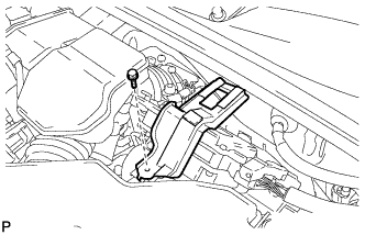
| 34. REMOVE POWER STEERING ECU ASSEMBLY |
Remove the bolt and ground cable terminal from the power steering ECU assembly.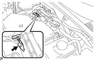
Release the locks of the 2 power steering ECU assembly connectors and disconnect the connectors.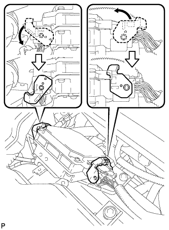
Separate the 2 wire harness clamps from the power steering ECU assembly.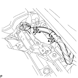
Remove the 2 bolts and the power steering ECU assembly.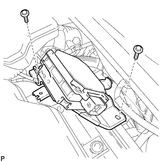
| 35. SEPARATE INVERTER RESERVE TANK SUB-ASSEMBLY |
Remove the 2 bolts and separate the inverter reserve tank sub-assembly.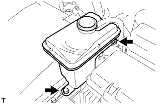
| 36. REMOVE POWER STEERING ECU BRACKET |
Remove the bolt, and disconnect the power steering ECU bracket.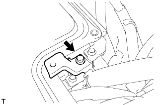
| 37. REMOVE INVERTER COVER |
Remove the bolt and interlock bracket.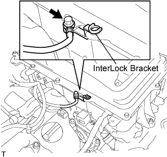
Insulate the removed terminal with insulating tape.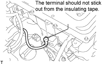
- NOTICE:
- Make sure that the terminal does not stick out from the insulating tape.
Remove the 12 bolts and inverter cover.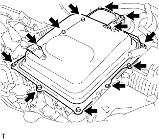
| 38. DISCONNECT W/ CONVERTER INVERTER ASSEMBLY |
- CAUTION:
- Wear insulating gloves.
- NOTICE:
- Make sure that the inverter converter is temporarily installed before working on the converter inverter assembly. (Click here)
- Insulate the removed terminals with insulating tape.
- Do not allow any foreign objects or waterdrops to enter the w/ converter inverter assembly.
- Make sure that the inverter converter is temporarily installed before working on the converter inverter assembly. (Click here)
Remove the 5 bolts, and disconnect the No.3 wire frame (high voltage cable of the rear motor) to the w/ converter inverter assembly.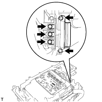
Remove the bolt and lift the lever to disconnect the No.3 wire frame from the w/ converter inverter assembly.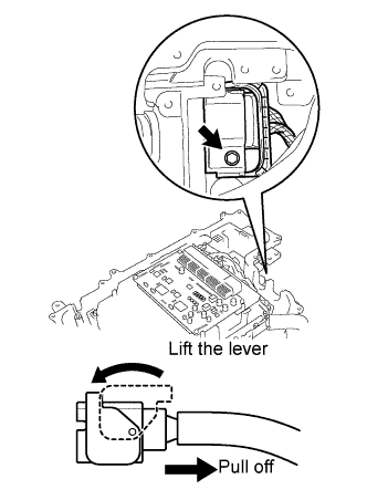
| 39. INSTALL INVERTER COVER |
Temporarily install the inverter cover with the 2 bolts to prevent any foreign objects or waterdrops from entering the w/ converter inverter assembly.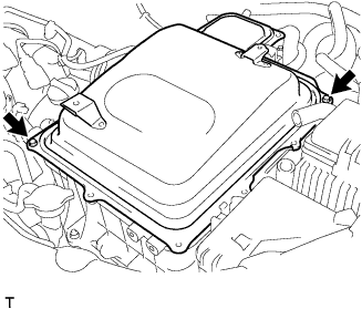
| 40. DISCONNECT REAR TRACTION W/ TRANSAXLE MOTOR ASSEMBLY |
- CAUTION:
- Wear insulating gloves.
- NOTICE:
- Insulate the removed terminals with insulating tape.
Disconnect the 2 connectors and clamp from the rear traction w/ transaxle motor assembly.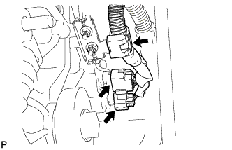
Remove the 2 nuts, and disconnect the No.3 wire frame from the rear traction w/ transaxle motor assembly.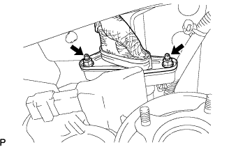
| 41. REMOVE WIRING HARNESS PROTECTOR |
Remove the 4 nuts and wiring harness protector.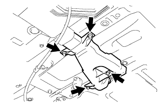
| 42. REMOVE NO.3 WIRE FRAME (for LHD) |
Remove the No.3 wire frame.
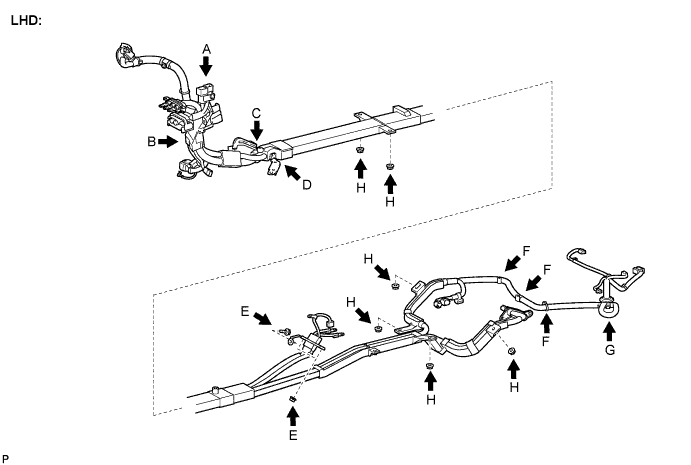
- CAUTION:
- Wear insulating gloves.
- NOTICE:
- Insulate the removed terminals with insulating tape.
Disconnect the 2 connectors and clamp as shown in the illustration. (A)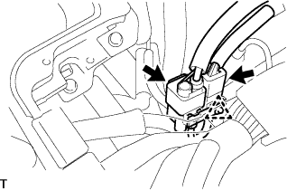
Disconnect the clamps as shown in the illustration. (B)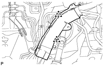
Disconnect the clamp as shown in the illustration. (C)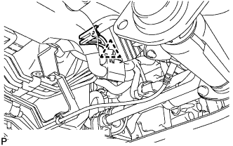
Disconnect the clamp as shown in the illustration. (D)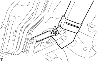
Remove the 2 nuts and bolt shown in the illustration and remove the No.3 wire frame. (E)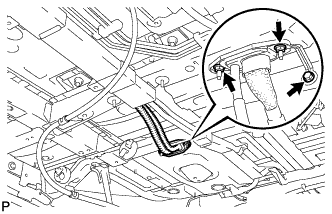
Disconnect the 3 clamps as shown in the illustration. (F)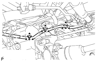
Disconnect the clamp shown in the illustration and remove the No.3 wire frame. (G)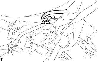
Remove the 6 nuts and No.3 wire frame. (H)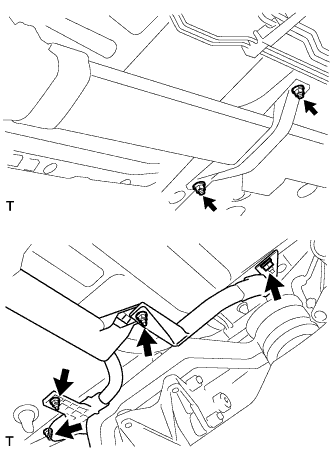
| 43. REMOVE NO.3 WIRE FRAME (for RHD) |
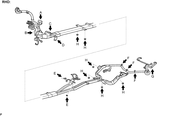
Remove the No.3 wire frame.
- CAUTION:
- Wear insulating gloves.
- NOTICE:
- Insulate the removed terminals with insulating tape.
Disconnect the 2 connectors and clamp as shown in the illustration. (A)
Disconnect the clamps as shown in the illustration. (B)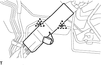
Disconnect the clamp as shown in the illustration. (C)
Disconnect the clamp as shown in the illustration. (D)
Remove the 2 nuts and bolt shown in the illustration and remove the No.3 wire frame. (E)
Disconnect the 3 clamps as shown in the illustration. (F)
Disconnect the clamp shown in the illustration and remove the No.3 wire frame. (G)
Remove the 6 nuts and No.3 wire frame. (H)